Stackable ribbed bottle system

a bottle system and ribbed technology, applied in the field of containers, can solve the problems of increasing the likelihood that the contents of the bottles will leak out of the bottles, the stackable bottles do not include, and the stackable bottles are not ideal, so as to improve the collapsibility of the bottle, increase the top load capacity, and strengthen the bottl

a bottle system and ribbed technology, applied in the field of containers, can solve the problems of increasing the likelihood that the contents of the bottles will leak out of the bottles, the stackable bottles do not include, and the stackable bottles are not ideal, so as to improve the collapsibility of the bottle, increase the top load capacity, and strengthen the bottl

US20090266782A1Inactive Publication Date: 2009-10-29LANE DEAN VINCENT

Image

  • Stackable ribbed bottle system
  • Stackable ribbed bottle system
  • Stackable ribbed bottle system

Examples


Embodiment Construction

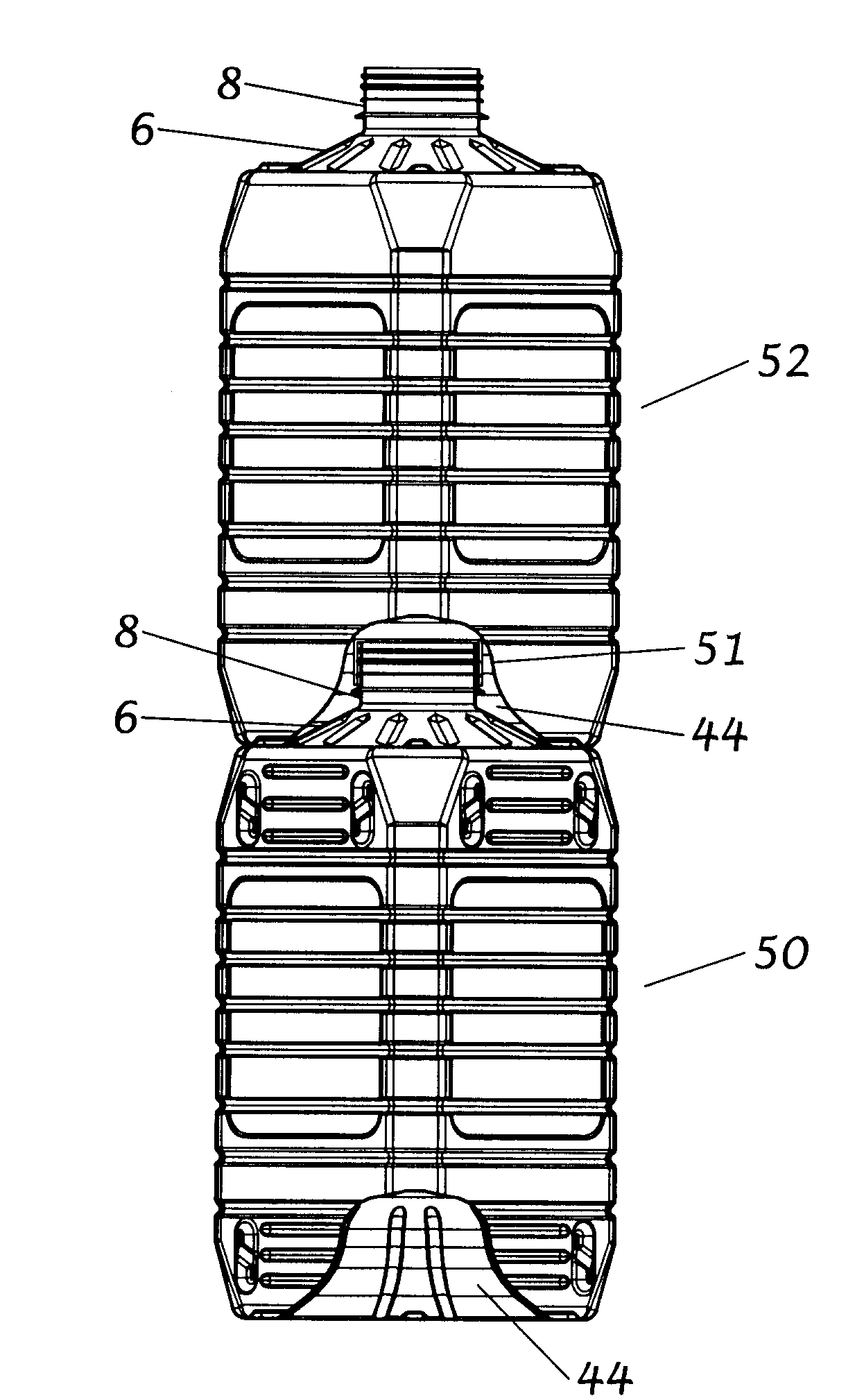
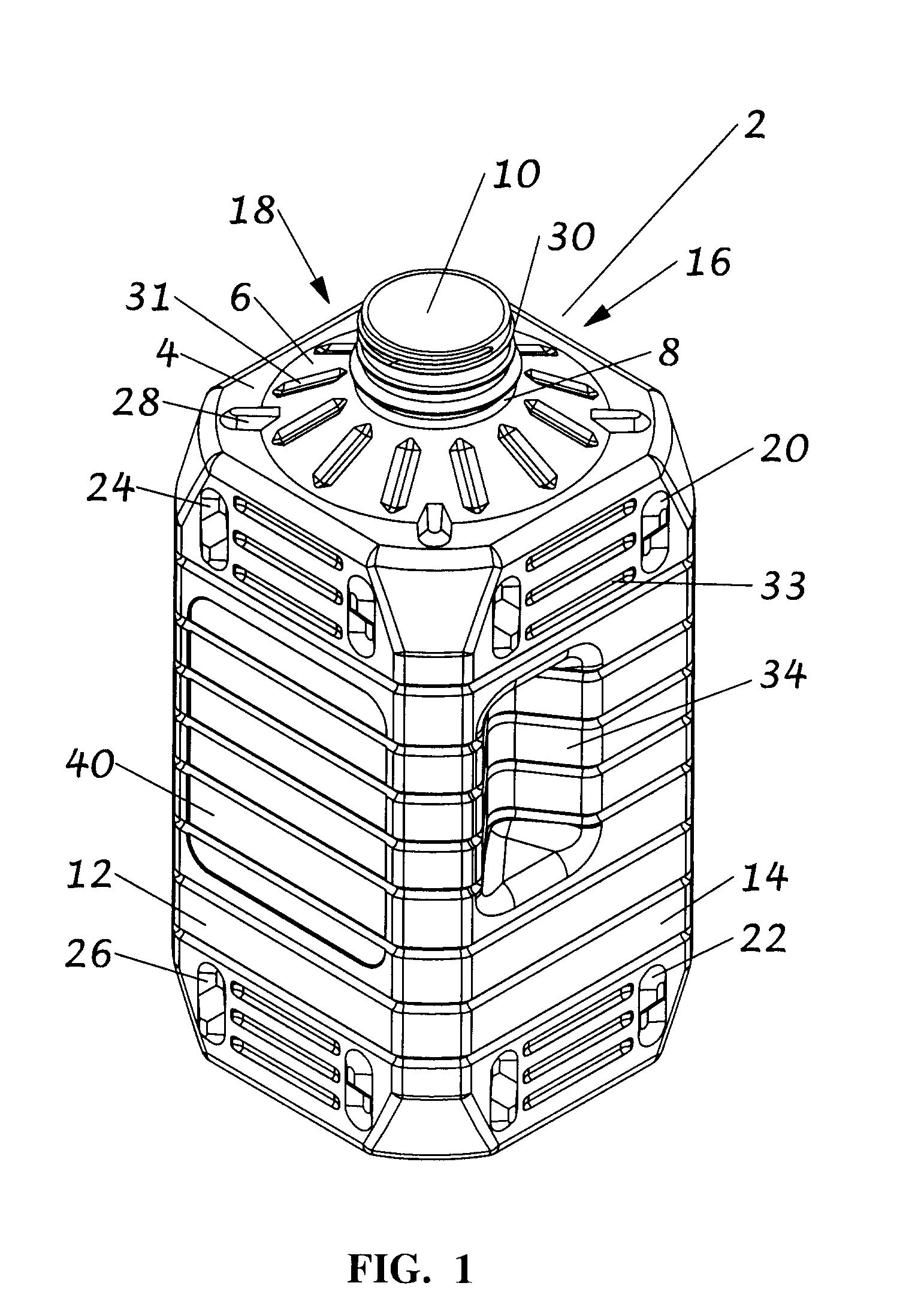
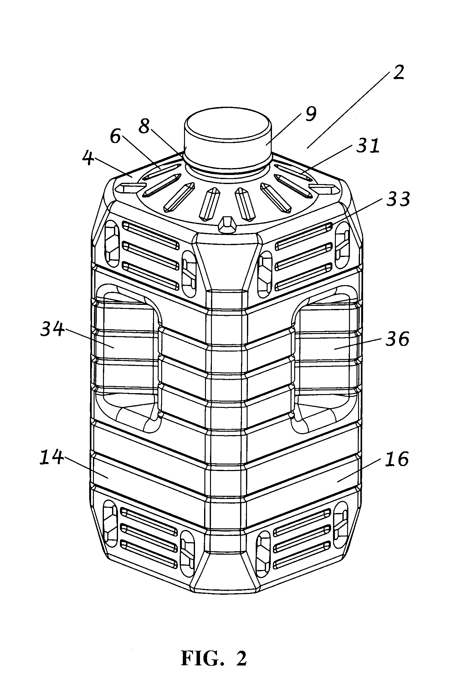
[0029]Referring first to FIGS. 1 to 3, a stackable bottle 2 according to the present invention comprises a storage compartment having an upper surface 4 with a conical ceiling 6, a centrally disposed neck 8 extending from the conical ceiling with an opening 10 therein, and a lower surface 42. The bottle has four side walls 12, 14, 16, 18, vertical interlocking means comprising side wall protrusions 20, 22 corresponding to side wall recesses 24, 26, and horizontal interlocking means comprising at least one upper surface protrusion 28 corresponding to at least one lower surface recess 46.

[0030]The side wall protrusions are of a size, relative to the size of the side wall recesses, which permits a releasable locational transition fit engagement of the protrusions into the recesses. Similarly, the upper surface protrusions are of a size, relative to the size of the lower surface recesses, which permits a releasable locational transition fit engagement of the protrusions into the recesse...


PUM


Abstract

A bottle having a storage chamber defined by spaced upper and lower surfaces and planar sidewalls; a conical ceiling in said upper surface having an opening at the top thereof; a conical convex recess in said lower surface for receiving the conical ceiling of the next adjacent bottle when stacking said bottles, and means for interlocking the sides and upper and lower surfaces of the bottles when stacked. The bottle may have ribs in the conical ceiling, conical recess and sidewalls for increasing top load resistance. A plurality of bottles may be assembled into a stable bottle stack with minimal packaging material.

Description

TECHNICAL FIELD[0001]The present invention relates generally to containers, and more particularly to a system of stackable bottles.BACKGROUND ART[0002]It is known to provide a storage bottle which permits stacking of bottles on the bottles' sides. Examples of such bottles include U.S. Pat. No. 4,892,207 to Cullis entitled: “Bottled Water Container”, U.S. Pat. No. 5,002,199 to Frahm entitled: “Stackable Bottle”, U.S. Pat. No. 4,308,955 to Schieser et al. entitled: “Interfitting, Stackable Bottles”; and U.S. Pat. No. 3,889,834 to Harris entitled: “Container Construction”. Such stackable bottles are not ideal as the sideways stacking of bottles may increase the likelihood that the contents of the bottles will leak out of the bottles, particularly where the bottle contents are liquid.[0003]It is also known to provide stackable bottles which permit the nesting of the neck of one bottle into a recess in the bottom of another bottle. Examples of such bottles include those described in U.S....

Claims


Application Information

Patent Timeline
29 Oct 2009
Publication
US20090266782A1
IPC
B65D21/00
CPC
B65D21/0202; B65D21/0231; B65D23/102; B65D2501/0081; B65D71/063; B65D2501/0027; B65D71/0096; B65D1/023
Inventors
LANE, DEAN VINCENT