Actuator Control Device, Actuator Control Method, Actuator, Robot Apparatus, and Computer Program

a technology of actuator control and control device, applied in the direction of programme control, electrical programme control, instruments, etc., can solve the problems of low compatibility of robot apparatuses which execute tasks while performing physical interaction with various outsides, inability to respond to external forces flexibly or precisely, and difficulty in controlling

Active Publication Date: 2009-11-05
SONY CORP
View PDF24 Cites 86 Cited by
  • Summary
  • Abstract
  • Description
  • Claims
  • Application Information

AI Technical Summary

Benefits of technology

[0020]In view of the above, it is desirable to provide excellent actuator control device and actuator control method which can suitably control driving of joint actuators by a force control method which directly controls a joint generation force, an actuator, a robot apparatus, and a computer program.

Problems solved by technology

However, the positional control is commonly called “hard control” because its basic purpose is to hold a position, and is not suitable for responding to an external force flexibly or for precisely performing “soft” control in terms of velocity or acceleration.
For example, robot apparatuses which execute a task while performing physical interaction with various outsides originally have low compatibility with the positional control.
On the other hand, the force control is apt to be influenced by a disturbance, and the control is not easy.
Friction or inertia which exists in a joint part becomes a biggest problem as a disturbance in the force control.
In contrast, the latter (especially friction) is hard to model and identify and becomes a factor which causes a large error.
According to this method, although high-response force control becomes possible, there is a problem that the motor becomes bigger or a sufficient joint force is not obtained.
In other words, in order to allow interaction in an arbitrary part of a whole body, expensive force sensors should be mounted in various places of the body.

Method used


Image

  • Actuator Control Device, Actuator Control Method, Actuator, Robot Apparatus, and Computer Program
  • Actuator Control Device, Actuator Control Method, Actuator, Robot Apparatus, and Computer Program
  • Actuator Control Device, Actuator Control Method, Actuator, Robot Apparatus, and Computer Program

Examples


Embodiment Construction

[0061]Hereinafter, embodiments of the present invention will be described in detail with reference to the drawings.

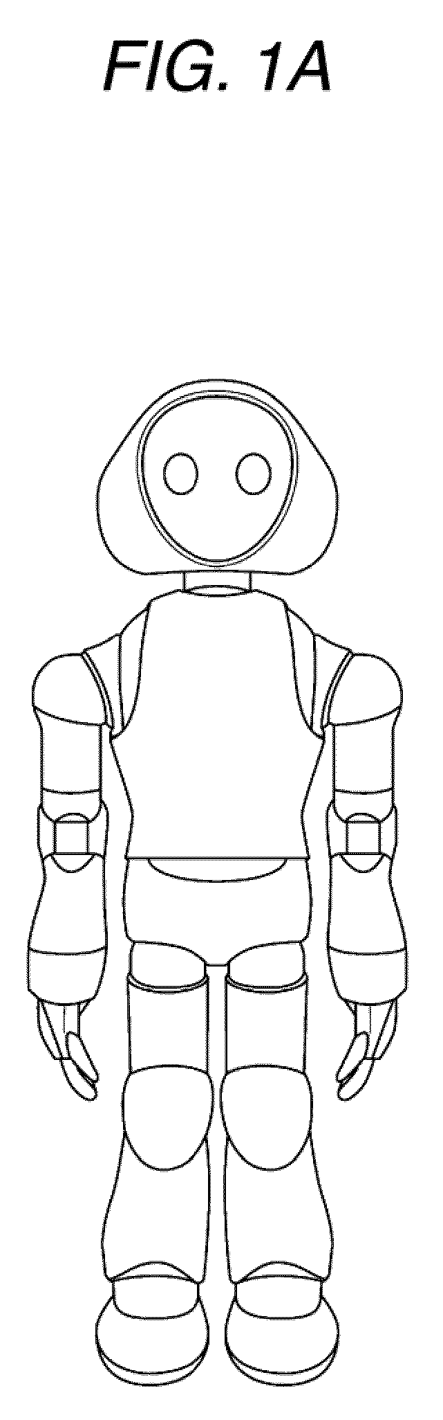
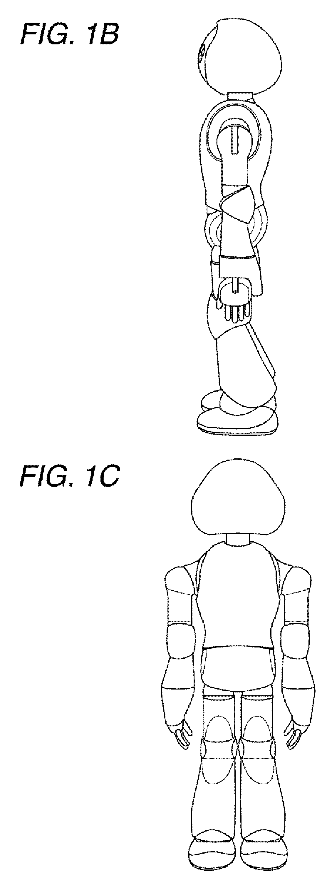
[0062]A front view, a left side view, a back view, a top view, a bottom view, and a perspective view of a humanoid robot to which the invention can be applied are shown in FIGS. 1A to L, and a front view, a left side view, a back view, a top view, a bottom view, and a perspective view of a head part of the robot are respectively shown in FIGS. 1A to 1L. A joint degree-of-freedom model of the humanoid robot shown in FIGS. 1A to 1L is shown in FIG. 2. In the humanoid robot shown, an upper body is connected to a pelvic part via two leg bodies as a moving means, and a waist joint. Two arm parts are connected to the upper body, and a head part is connected to the upper body via a neck joint.

[0063]The right and left leg bodies are provided with a total of six degrees of freedom including three degrees of freedom of a hip joint, one degree of freedom of a knee joint, and two d...


PUM


Abstract

There is provided an actuator control device for force-controlling a joint driving actuator according to a commanded joint force command value τa. The actuator control device includes a joint value detecting means for detecting a joint value q at an output stage of the actuator, an action force detecting means for detecting an action force τe in a joint driving direction at the output stage of the actuator, and a driving force determining means for determining an instructed driving force τ to the actuator, on the basis of an ideal response model of the actuator which specifies the relationship of a joint value acceleration target value achieved as the actuator responds ideally when the joint force command value τa, the action force τe, and a joint value velocity obtained by time-differentiating the joint value q are given.

Description

BACKGROUND OF THE INVENTION[0001]1. Field of the Invention[0002]The present invention relates to an actuator control device and an actuator control method which control actuators used for driving or the like of joint parts of a robot, an actuator, a robot apparatus, and a computer program, and particularly, to an actuator control device and an actuator control method which control driving of joint actuators by a force control method which directly controls a joint generation force, an actuator, a robot apparatus, and a computer program.[0003]More specifically, the present invention relates to an actuator control device and an actuator control method which perform force control suitable for physical interaction with a human being while coping with factors of disturbances whose modeling or identifying is difficult, such as friction or inertia, which exists in joint parts, an actuator, a robot apparatus, and a computer program, and particularly, to an actuator control device and an act...

Claims


Application Information

Patent Timeline
Patent Type & Authority Applications(United States)
IPC IPC(8): B25J9/02B25J17/00B25J18/00G05B19/04B62D57/032G06F19/00B25J13/08G05D17/02H02P29/00
CPCB25J9/1633Y10T74/20317G05B2219/39319G05B2219/39355
Inventor NAGASAKA, KENICHIRO
Owner SONY CORP
Why Eureka
Try Eureka