Touch input device

a technology of input device and touch sensor, which is applied in the direction of instruments, computing, electric digital data processing, etc., can solve the problems of difficult to identify the position degrade the quality of displayed images, and difficult to detect the location of the stylus on one set of electrodes, so as to reduce the effect of the touch sensor device on the output of an underlying display device, reduce the effect of capacitance change, and reduce the effect of the touch sensor

Inactive Publication Date: 2009-11-05
INNOLUX CORP
View PDF17 Cites 66 Cited by
  • Summary
  • Abstract
  • Description
  • Claims
  • Application Information

AI Technical Summary

Benefits of technology

[0025]In one example, each group of electrodes comprises an adjacent group of electrodes. This means that each sense electrode is effectively an arrangement of electrodes spread over an area using a higher resolution array of electrodes. The high resolution electrodes can thus be considered to be sub-electrodes. Because these sense sub-electrodes have a finer resolution than the resolution being sensed (for example finer than size of the object being detected), there is a more gradual shift in capacitance change from one sense electrode arrangement to the next as the input moves. However, the sense electrode arrangements can still occupy a small area and therefore the effect of the touch sensor device on the output of an underlying display device can be minimised. The touch sensor capacitance signal is stronger when the input position is between sense electrode arrangement positions.

Problems solved by technology

The presence of the sense electrodes may therefore degrade the quality of the displayed images particularly when moving images are being viewed.
A further concern is that when the object to be sensed is significantly smaller than the sense electrode pitch, this will affect the way in which the capacitance values change with the position of the object, making it difficult to uniquely locate the position of the object when it is centred on one of the sense electrodes.
This may make it difficult to detect the location of the stylus on one set of electrodes, for example the A electrodes, when the stylus is centred over one of the other set of electrodes, for example the B electrodes.
This will make it difficult to detect which of the A electrodes the object is closest to.
However, the electrode shape required to produce the desired sensor characteristics may not be consistent with the pattern required to minimize the visibility of the sense electrodes.

Method used


Image

  • Touch input device
  • Touch input device
  • Touch input device

Examples


Embodiment Construction

[0045]The following description is of the contemplated mode of carrying out the invention. This description is made for the purpose of illustrating the general principles of the invention and should not be taken in a limiting sense. The scope of the invention is determined by reference to the appended claims.

[0046]Wherever possible, the same reference numbers are used in the drawings and the descriptions to refer to the same or like parts.

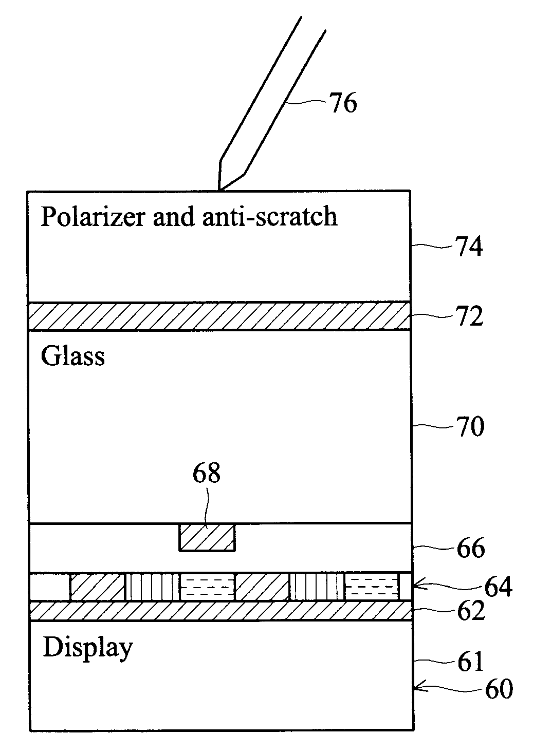
[0047]The invention provides a touch sensor input device in which capacitive sensing electrodes are arranged as connected groups of electrodes, so that the individual electrodes have smaller pitch than the sensing resolution. This improves the ability to determine uniquely the location of a touch input for all positions. The smaller electrode pitch matches the design of the display, so that visual artefacts caused by the sense electrode structure are reduced.

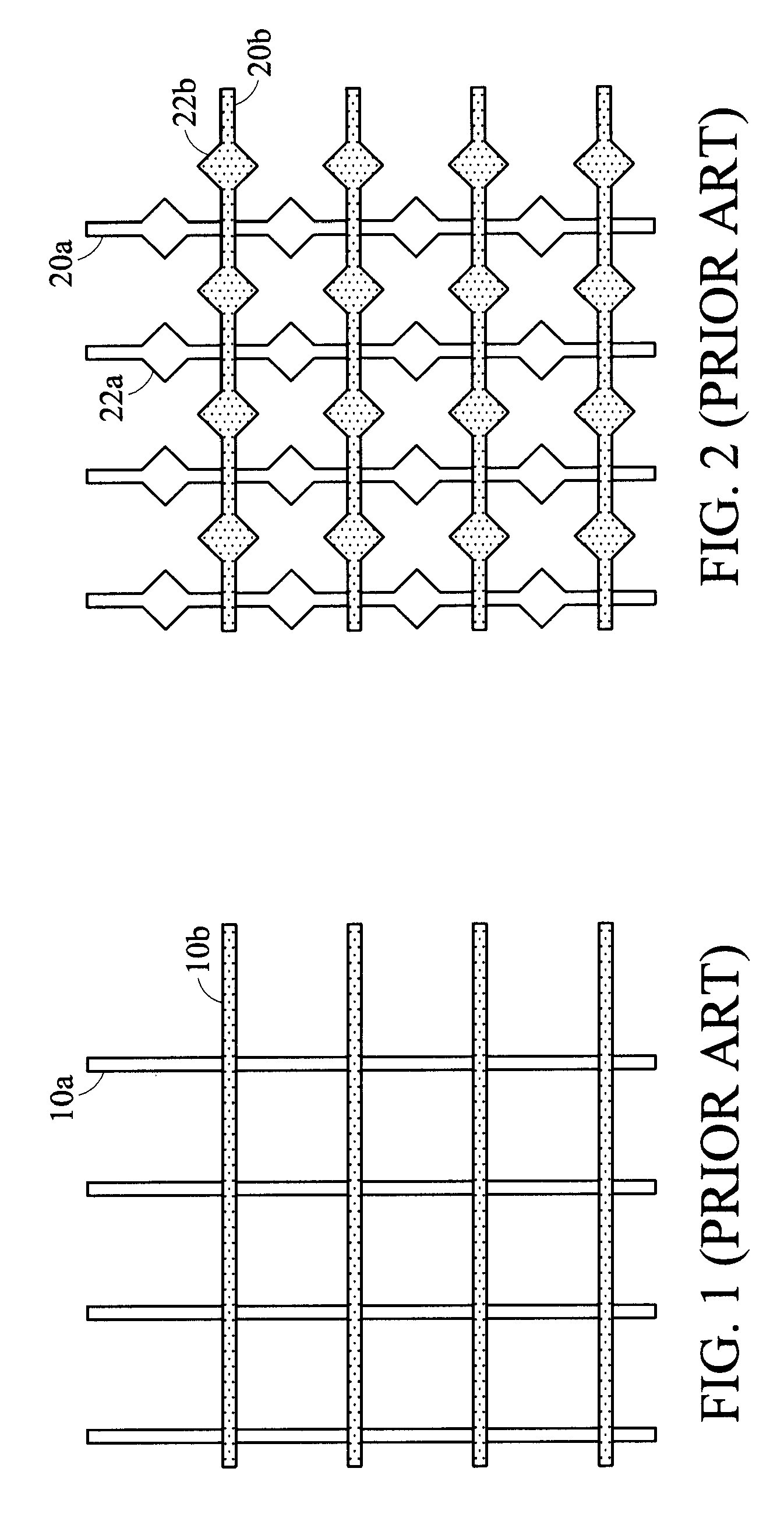
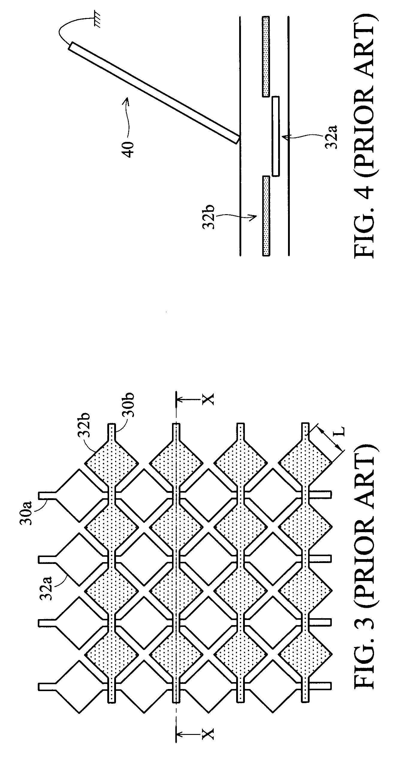
[0048]Before explaining the invention in detail, an example will be provided of the type of...


PUM


Abstract

A touch sensor input device includes a first and second array of electrodes, the electrodes in the first array being orthogonal to the electrodes in the second array. A capacitor sensing arrangement senses an electrode capacitance signal which varies in the presence of a touch input. The capacitance signals for groups of electrodes in each array are combined in order to derive respective individual sense signals. This arrangement has electrodes with a finer resolution than the sensing resolution, and this gives improved ability to sense accurately the position of the touch input.

Description

CROSS REFERENCE TO RELATED APPLICATIONS[0001]This application claims the benefit of U.S. Provisional Application No. 61 / 125,917, filed on Apr. 30, 2008, and U.S. Provisional Application No. 61 / 125,963, filed on Apr. 30, 2008, the entirety of which are incorporated by reference herein.[0002]This application claims priority of EP Patent Application No. 09152695.4, filed on Feb. 12, 2009, the entirety of which is incorporated by reference herein.BACKGROUND OF THE INVENTION[0003]1. Field of the Invention[0004]This invention relates to touch input devices, for example for use in display devices with touch screens.[0005]2. Description of the Related Art[0006]Touch screens are becoming increasingly common in consumer electronics applications where an LCD display is present in a device e.g. mobile phone, PDA or camera. User interaction via a touch screen saves the space required for key inputs and therefore allows a larger display area for a given size of device. The touch screen provides a...

Claims


Application Information

Patent Timeline
Patent Type & Authority Applications(United States)
IPC IPC(8): G06F3/041
CPCG06F3/044G06F3/0412G06F3/0446G06F3/047
Inventor EDWARDS, MARTIN JOHNAYRES, JOHN RICHARDBRAMANTE, NICOLA
Owner INNOLUX CORP
Why Eureka
Try Eureka