

Bus bar
a technology of bus bars and terminals, applied in the field of bus bars, can solve the problems of considerable burden on each terminal, and achieve the effect of reducing the burden on each terminal
- Summary
- Abstract
- Description
- Claims
- Application Information
AI Technical Summary
Benefits of technology
Problems solved by technology
Method used
Image

Examples
first embodiment
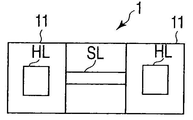
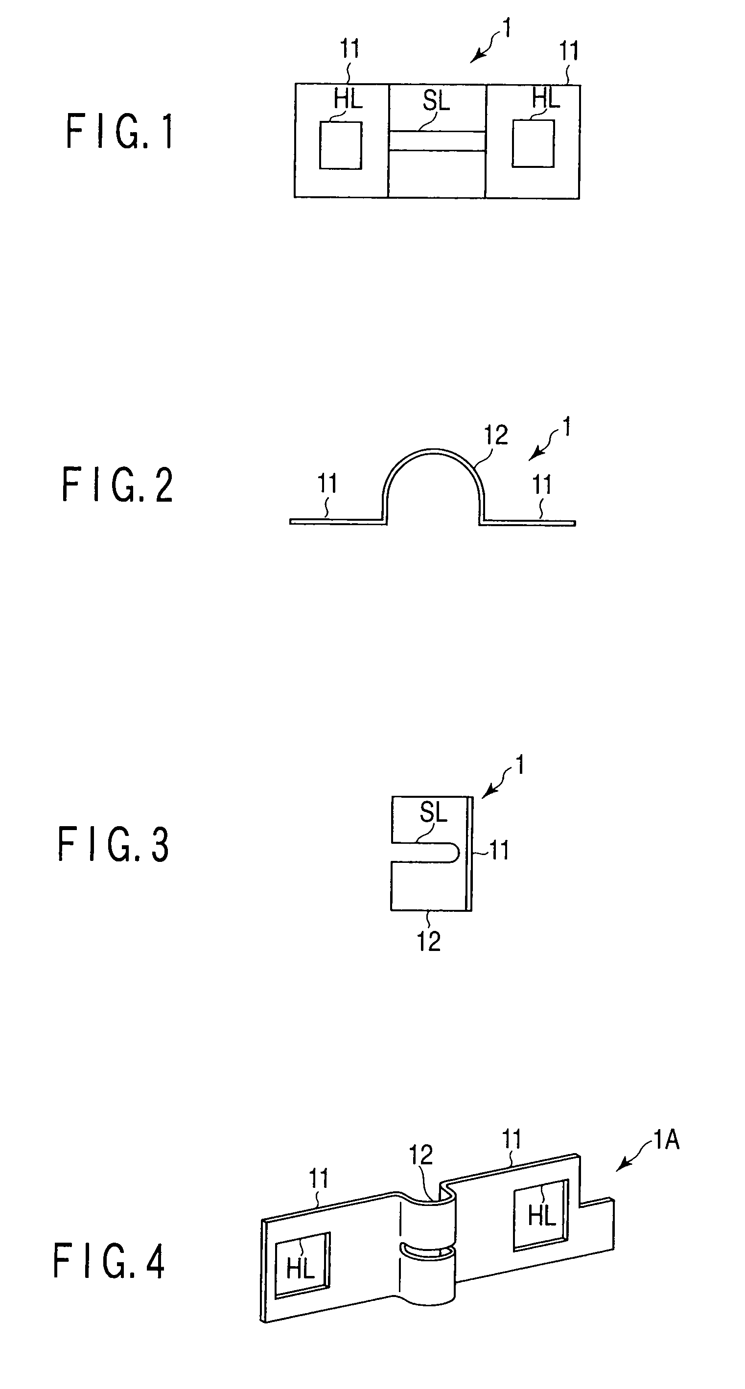
[0037]FIG. 1 is a top view showing a shape of an upper surface of a bus bar 1 according to a first embodiment of the present invention. FIG. 2 is a front view showing a shape of a front surface of the bus bar 1 according to this embodiment. FIG. 3 is a side view showing a shape of a side surface of the bus bar 1 according to this embodiment. It is to be noted that like reference numerals denote like parts to omit a detailed explanation thereof, and different parts will be mainly described. A tautological explanation will be likewise omitted in the subsequent embodiments.
[0038]In the bus bar 1, two connecting portions 11 that are connected with terminals respectively provided to two batteries and a convex portion 12 that is formed into a convex shape between these two connecting portions 11 are provided. In the bus bar 1, the two connecting portions 11 and the convex portion 12 are formed by molding one tabular metal plate (a conductive plate).
[0039]A hole HL is formed in the connect...
second embodiment
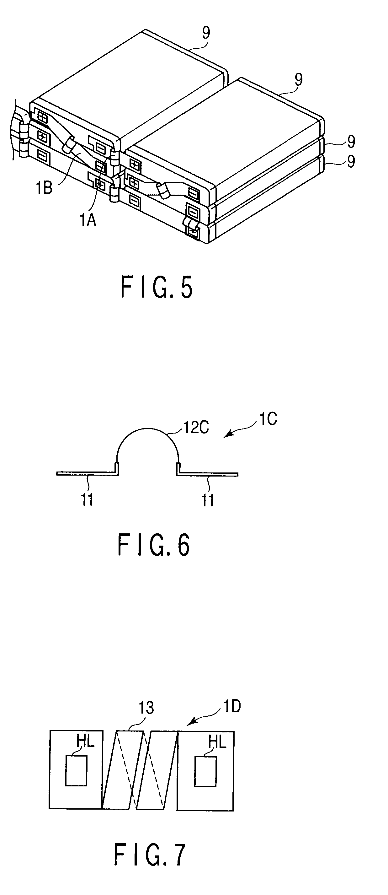
[0049]FIG. 6 is a front view showing a shape of a front surface of a bus bar 1C according to a second embodiment of the present invention.
[0050]In the bus bar 1C, a convex portion 12C is formed by molding a tabular material thinner than each connecting portion 11 in place of the convex portion 12 in the bus bar 1 according to the first embodiment. Other points are the same as those in the bus bar 1.
[0051]According to this embodiment, it is possible to obtain the following functions and effects in addition to the functions and effects provided by the first embodiment.
[0052]Since the convex portion 12C in the bus bar 1C is formed by molding the tabular material thinner than each connecting portion 11, a force in a connecting direction of terminals can be further reduced as compared with the bus bar 1 according to the first embodiment.
third embodiment
[0053]FIG. 7 is a top view showing a shape of an upper surface of a bus bar 1D according to a third embodiment of the present invention. FIG. 8 is a front view showing a shape of a front surface of the bus bar 1D according to this embodiment. FIG. 9 is a side view showing a shape of a side surface of the bus bar 1D according to this embodiment.
[0054]In the bus bar 1D, a spiral portion 13 is formed in place of the convex portion 12 in the bus bar 1 according to the first embodiment. In the bus bar 1D, two connecting portions 11 and the spiral portion 13 are formed by molding one tabular metal plate (a conductive plate). Other points are the same as those in the bus bar 1.
[0055]The spiral portion 13 is extended to be wound around a line in a connecting direction of terminals of two batteries. The spiral portion 13 plays a role of buffering forces in various directions that are applied to the terminals of the two batteries.
[0056]According to this embodiment, a spring constant of the bu...
PUM
 Abstract
Description
Claims
Application Information