Pure air blast fuel injector

a fuel injector and air blast technology, which is applied in the ignition of the turbine/propulsion engine, engine starters, lighting and heating apparatus, etc., can solve the problems of insufficient amount of fuel atomized, difficulty in engine startup, and difficulty in initiation or sustainablity of ignition

Active Publication Date: 2009-11-12
ROLLS ROYCE PLC
View PDF15 Cites 46 Cited by
  • Summary
  • Abstract
  • Description
  • Claims
  • Application Information

AI Technical Summary

Problems solved by technology

While pure airblast nozzles can provide for clean fuel combustion when the engine compressor is spooled up, difficulties can arise during engine startup.
However, during engine startup the compressor is not fully spooled up and thus the air pressures provided to the nozzle during engine startup are not always high enough to provide the necessary atomizing air blast.
Therefore, the amount of fuel atomized can be insufficient to initiate or sustain ignition.
Thus it can be quite difficult to start an engine using only traditional pure air blast nozzles.
Another problem during startup for traditional airblast nozzles is that when the startup air pressure is too low to filly atomize the fuel flowing from the nozzle, significant amounts of fuel can issue from the nozzle without being atomized.
Liquid fuel drooling from the nozzle constitutes waste of fuel and can cause poor emissions as well as complications that can arise from fuel pooling in undesirable locations of the engine.
However, while these solutions can be used to facilitate engine start up, they can also add significantly to the cost and weight of the engine.
However, piloted airblast nozzles tend to lack the superior thermal management inherent in pure airblast nozzles.
Piloted airblast nozzles also fail to achieve identical spray characteristics with pure airblast nozzles because the pressure atomizing circuit mixes with the airblast spray.

Method used


Image

  • Pure air blast fuel injector
  • Pure air blast fuel injector
  • Pure air blast fuel injector

Examples


Embodiment Construction

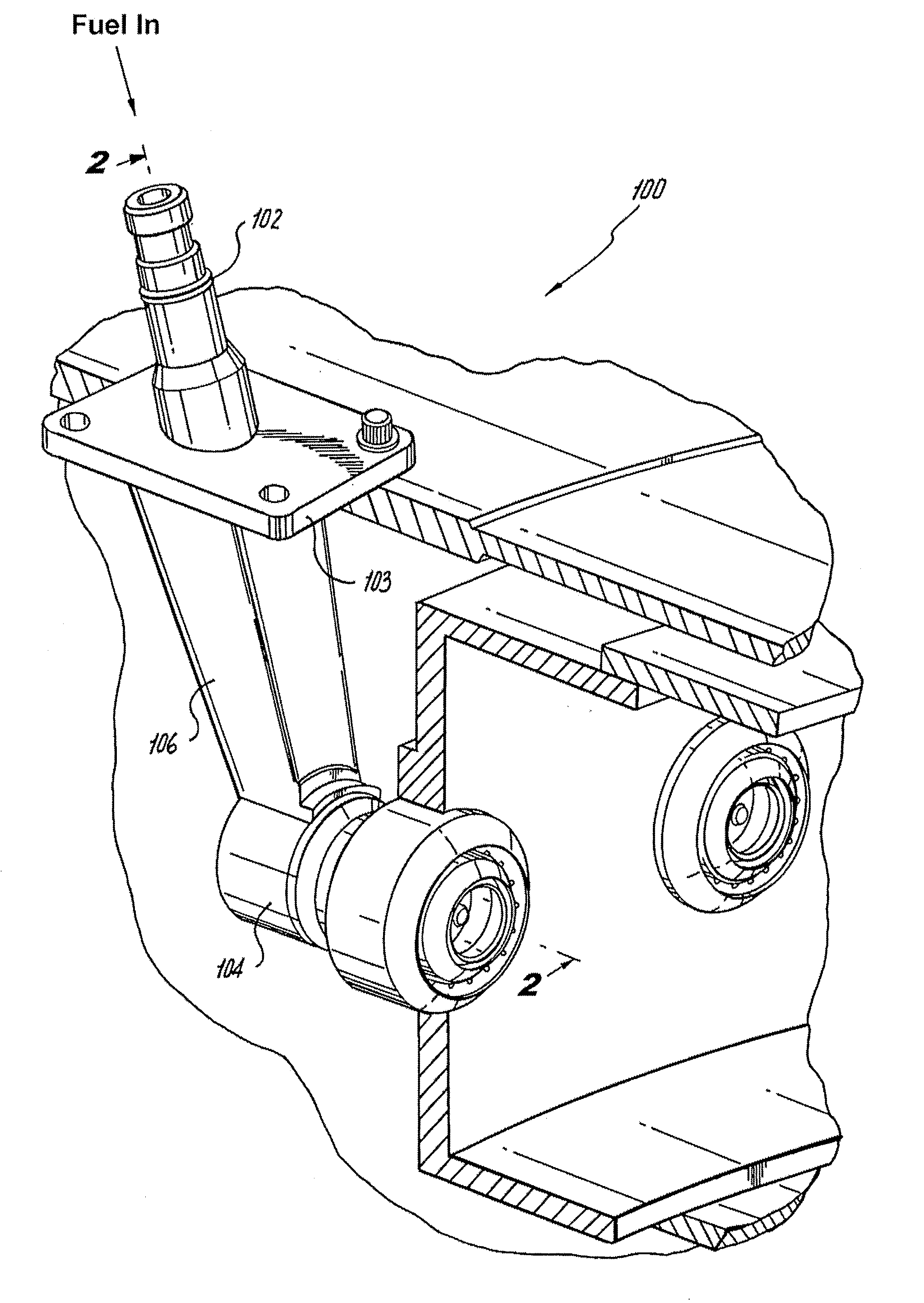
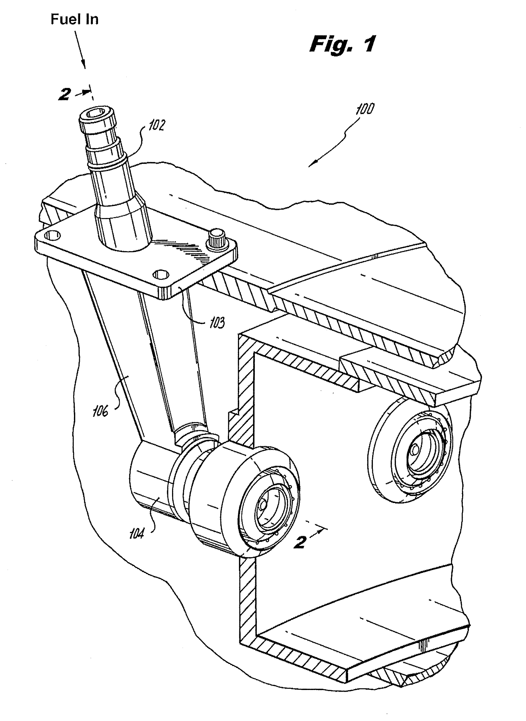
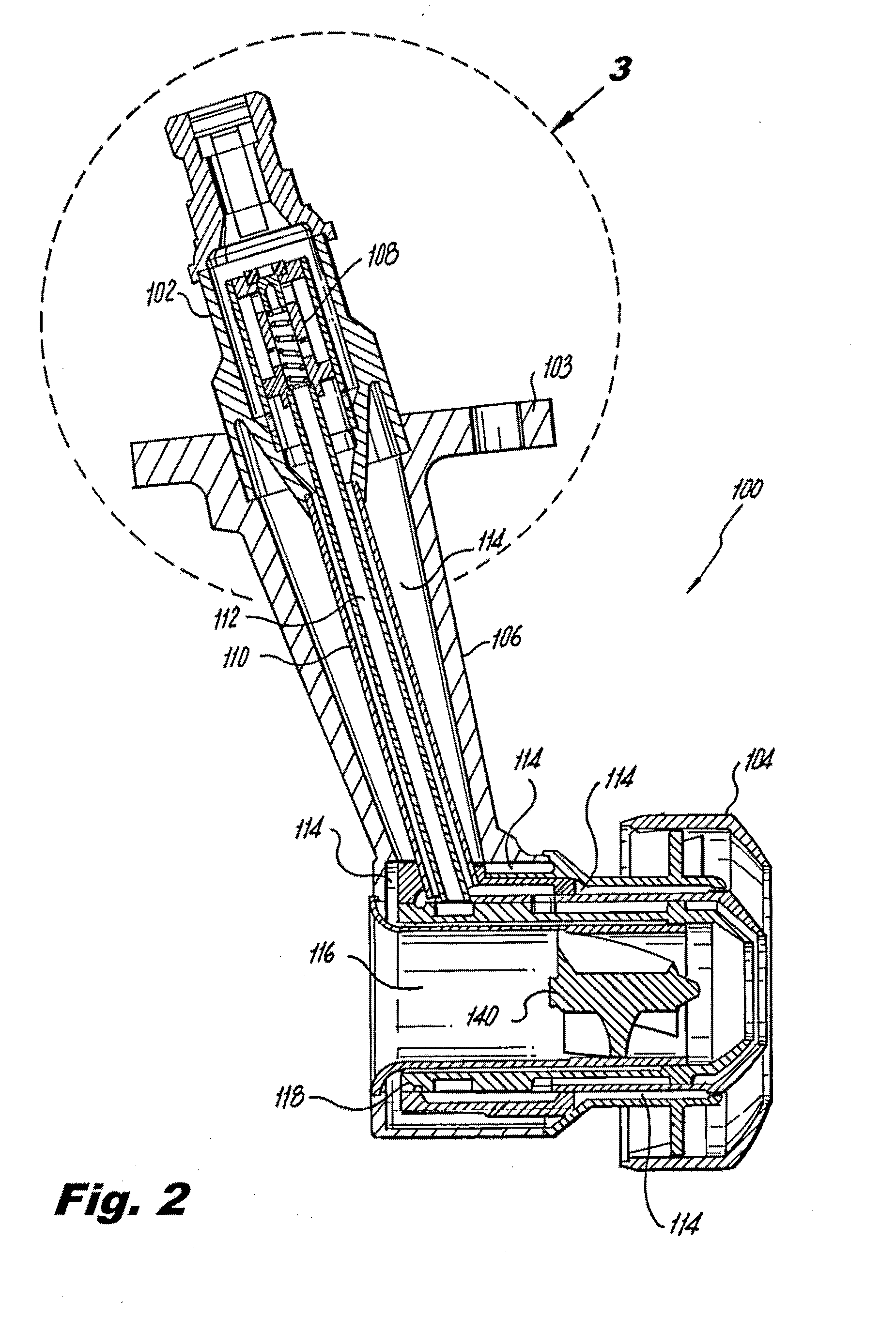
[0028]Reference will now be made to the drawings wherein like reference numerals identify similar structural features or aspects of the subject invention. For purposes of explanation and illustration, and not limitation, a partial view of an exemplary embodiment of the injector in accordance with the invention is shown in FIG. 1 and is designated generally by reference character 100. Other embodiments of injectors and nozzles in accordance with the invention, or aspects thereof, are provided in FIGS. 2-3 and 5-9, as will be described. The system of the invention can be used in gas turbine engines, or in any other suitable application, for enhanced fuel atomization during engine start up and sustained stable combustion.

[0029]As shown in FIG. 1, injector 100 includes a fuel inlet fitting 102 and a nozzle body 104 connected to each other by a feed arm 106. Fuel inlet fitting 102 is provided at an upstream end of injector 100 for receiving fuel to be atomized for combustion and includes...


PUM


Abstract

An air blast fuel injector for a gas turbine engine includes an elongate feed arm having an inlet fitting for receiving fuel and for distributing the fuel to first and second fuel delivery conduits extending through the feed arm. A nozzle body is operatively connected to the feed arm. The nozzle body includes an on-axis inner air circuit and fuel circuitry radially outboard of the inner air circuit for delivering fuel to a fuel swirler outboard of the inner air circuit. The fuel circuitry includes a first fuel circuit configured and adapted to deliver fuel to the fuel swirler from the first fuel conduit of the feed arm and a second fuel circuit configured and adapted to deliver fuel to the fuel swirler from the second fuel conduit of the feed arm.

Description

BACKGROUND OF THE INVENTION[0001]1. Field of the Invention[0002]The present invention relates to fuel injectors and nozzles, and more particularly, to pure airblast fuel injectors and nozzles for gas turbine engines.[0003]2. Description of Related Art[0004]Pure airblast nozzles are in wide use among engine manufacturers, particularly in aircraft engines. Pure airblast nozzles create favorable air / fuel mixtures and have spray characteristics that produce combustion qualities desirable for low emissions and high engine efficiencies. A typical pure airblast injector has one fuel circuit. Fuel can be directed from an injector inlet fitting to a fuel swirler through a fuel tube. At the fuel swirler, the fuel can be split into a multitude of discrete paths, all of which discharge into the combustor. These discrete paths are all fluidly connected and are thus all part of a single fuel circuit.[0005]One example of a pure airblast fuel injector is described in U.S. Pat. No. 6,622,488 to Mans...

Claims


Application Information

Patent Timeline
Patent Type & Authority Applications(United States)
IPC IPC(8): F02C7/22
CPCF02C7/222F02C7/228F23D2900/11101F23D11/107F23D2900/00015F02C9/34F02C7/26F23R3/286F23R3/346
Inventor CAPLES, MARK A.
Owner ROLLS ROYCE PLC
Why Eureka
Try Eureka