
Battery forklift drive unit

Inactive Publication Date: 2009-11-12
KOMATSU LTD
View PDF4 Cites 24 Cited by
  • Summary
  • Abstract
  • Description
  • Claims
  • Application Information

AI Technical Summary

Benefits of technology

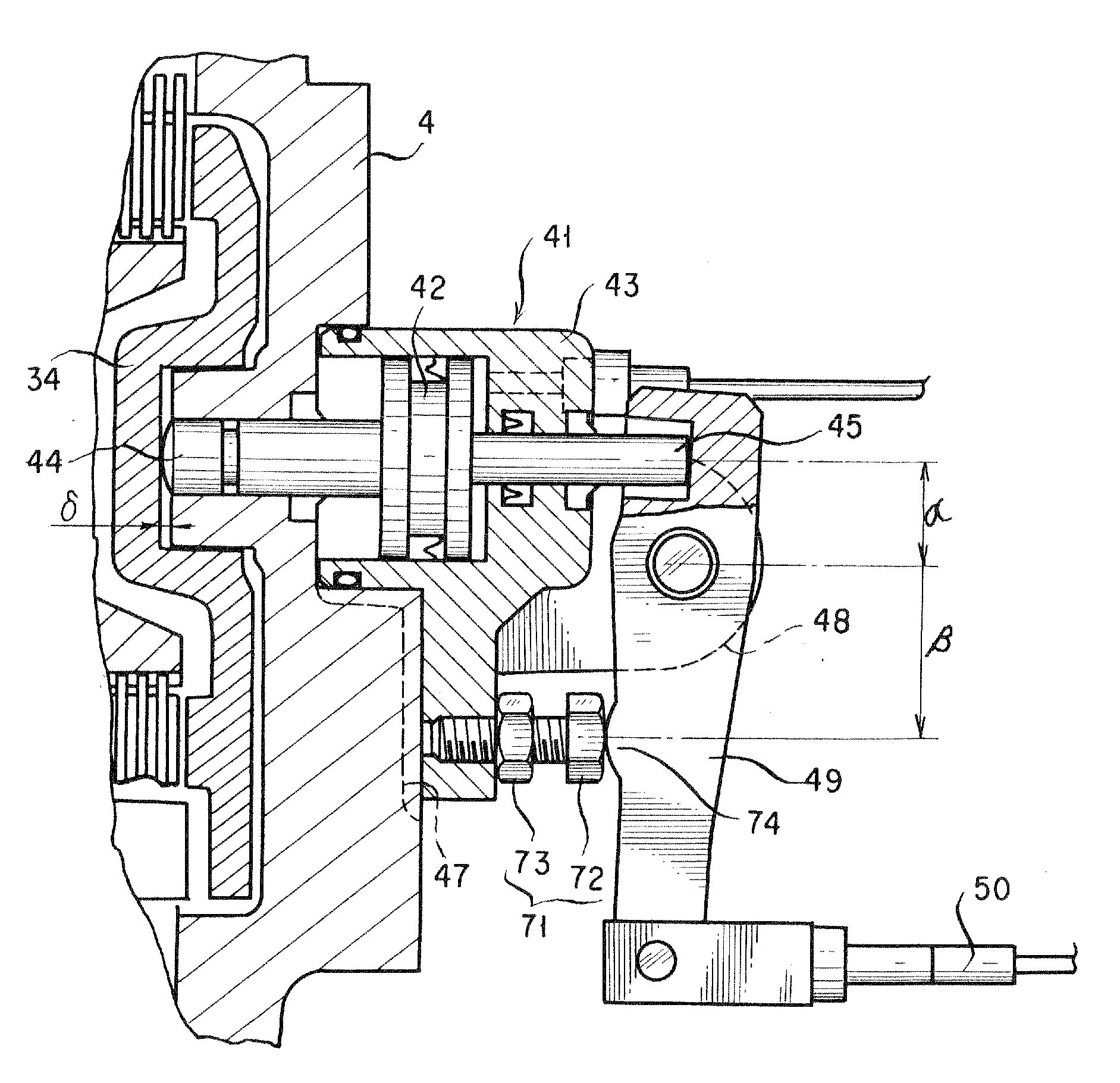
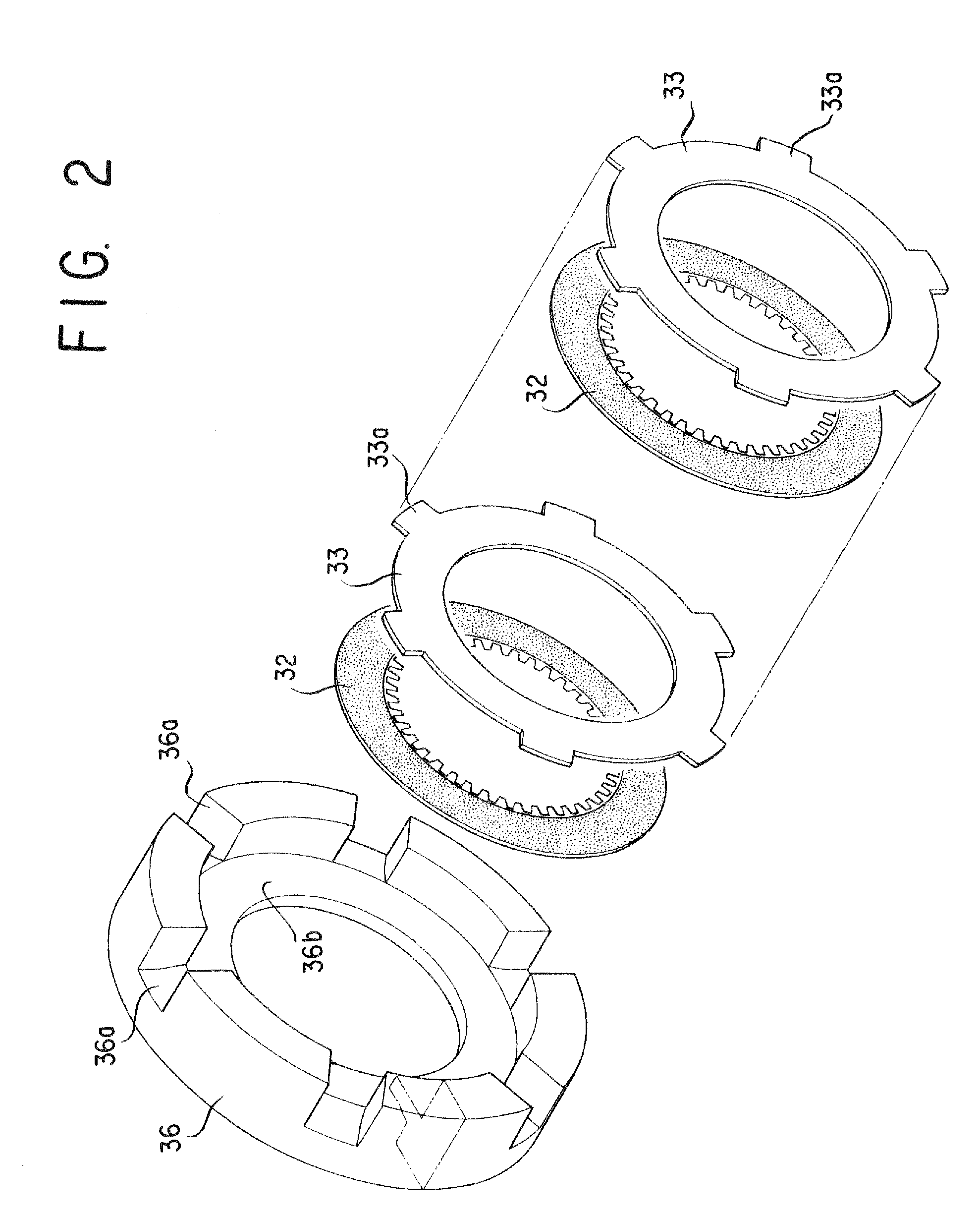
[0012]According to the present invention wherein the second gear included in the drive case is formed inwards with a space in which a wet type brake section is disposed, the need for a large space in which to dispose brakes in the vicinities of conventional drive units is eliminated, thereby permitting to achieve making the vicinities of drive units compact in a battery forklift.
[0013]Also, it is possible for the wet type brake section to be completely covered within the drive case and thus to prevent entry of mud, water and the like externally into the wet type brake section, hence largely mitigating problems such as of braking failure.
[0014]Also, by providing the clearance adjuster that adjusts the braking clearance in the inner and outer disks in the wet type brake section, it is possible to maintain the braking clearance in the inner and outer disks easily at a proper value when they are assembled or used to wear and consequently to eliminate various troubles in the wet type brake section. Moreover, since adjusting by the brake clearance adjuster is sufficient to adjust the brake clearance in the wet type brake section, it is possible to achieve a substantial simplification in operations to adjust the brake clearance in its assembling and during its use and it thus becomes possible to allow an operator to drive the vehicle at ease on an optimum constant adjustment of the brake clearance.

Problems solved by technology

As mentioned above, a pair of drive units for the conventional battery forklift in which left and right drive motors have dry single disc brakes fitted thereto at their sides which are opposed to each other, have required a large space between the left and right drive motors for receiving the dry single disc brakes which are large, thus presenting the problem that the drive units as a whole must become large sized.
Especially, giving rise to the problem that the size must become large in the left-and-right direction that is widthwise of the vehicle body, there has been a hindrance to making vicinities of drive units compact in a battery forklift.

Method used


Image

  • Battery forklift drive unit
  • Battery forklift drive unit
  • Battery forklift drive unit

Examples


Embodiment Construction

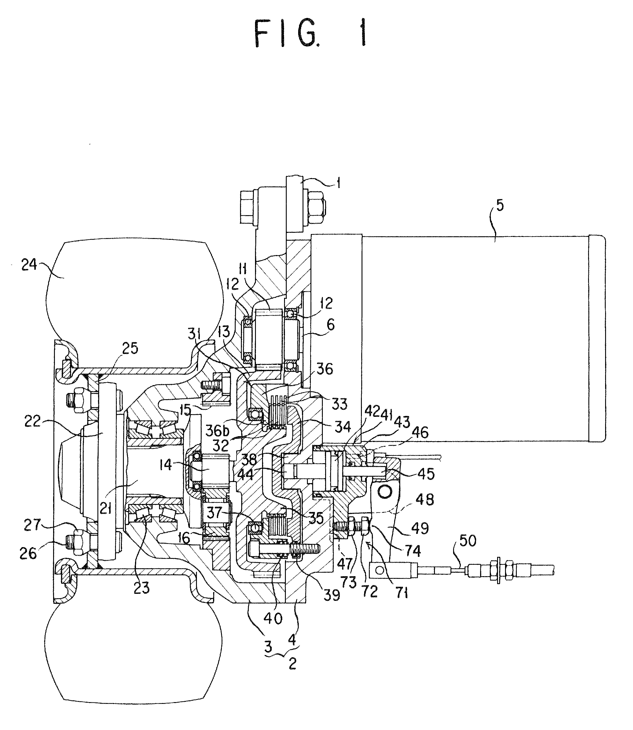
[0035]An explanation is given of a first form of implementation of the present invention for a battery forklift drive unit. As a pair of drive units are arranged so as to be opposed to each other at the left and right hand sides of the body of a vehicle (forklift), only one at the left or right hand side will be mentioned and mention of the other of an identical structure will be omitted.

[0036]As shown in FIG. 1, a drive case 2 which is fastened to the vehicle body 1 comprises a hollow, substantially frusto-conical case 3 and a generally disk-like cover 4 fastened to the case 3 and is hollowed, forming a space inside thereof. In upper part of the drive case 2, a drive motor 5 is fastened to the cover 4 inside the vehicle body so that a motor shaft 6 of the drive motor 5 projects inside the drive case.

[0037]And, in the drive case 2, the motor shaft 6 of the drive motor 5 is spline-fitted with a first gear 11. The first gear 11 is rotatably supported via a bearing 12 by the case 3 and...


PUM


Abstract

The invention is aimed at providing a battery forklift drive unit which makes a large space unnecessary for disposing brakes in the vicinities of drive units, thereby to achieve making the vicinities of drive units compact in a battery forklift. To this end, a second gear disposed in a drive case of the drive unit is formed inside with a space in which a wet type brake section is disposed and the wet type brake section comprises an inner disk whose entire inner periphery is attached to the second gear, an outer disk which lies opposite to the inner disk and whose entire outer periphery is attached to a side of the drive case, and a pressure plate for pressing together the inner and outer disks lying opposite to each other.

Description

TECHNICAL FIELD[0001]The present invention relates to a battery forklift drive unit and, more specifically, to an improvement in battery forklift drive units in which a brake is disposed inside of a drive unit, thereby to achieve making the vicinities of drive units compact in a battery forklift.BACKGROUND ART[0002]So far, a pair of drive units in a battery forklift as shown in FIG. 19 include a left and a right drive case 82 and 82, respectively, which are fastened to the body 81 of a forklift, the left and right drive cases 82 and 82 having a pair of drive motors 83 and 83 fastened thereto, respectively, which are opposed to each other. And, in the left and right drive cases 82 and 82, the motor shaft 84 of each of the left and right drive motors 83 and 83 is fitted with a first gear 85 which is meshed with a second gear 86 which is in turn connected via a plurality of gears to a carrier 87 so that power generated by the drive motor 83 is transmitted via the first and second gears...

Claims


Application Information

Patent Timeline
IPC IPC(8): F16D55/40
CPCB60K7/0007F16D2125/64B60K2007/0046B60K2007/0061B60L2220/46B60T1/005B60T1/062B60Y2200/15B66F9/07531B66F9/24F16D65/186F16D2121/02F16D2121/14F16D2123/00F16D2125/38B60K17/046F16D55/40B60K7/00B66F9/075
Inventor UENO, KAZUNORI
Owner KOMATSU LTD
Learn More