Banknote recognition and counting machine and banknote recognition and counting method

Inactive Publication Date: 2012-01-05
GLORY KOGYO KK
View PDF2 Cites 11 Cited by
  • Summary
  • Abstract
  • Description
  • Claims
  • Application Information

AI Technical Summary

Benefits of technology

[0029]According to the banknote recognition and counting method, the judgment for the banknotes, by using the first judgment threshold value is first performed, and then the judgment, by using the second threshold value, is performed for the banknotes, respectively fed to the reject unit after the judgment performed by using the first judgment threshold value. Then, information, which relates to the total sum of a count result on the banknotes, respectively judged to be true upon the judgment for the banknotes performed by using the first judgment threshold value and another count result on the banknotes, respectively judged to be true upon the judgment performed by using the second judgment threshold value, is outputted. Therefore, the need for inputting the count result on the banknotes, by manual input or the like means, can be eliminated, upon performing t

Problems solved by technology

However, in the money handling machine disclosed in the above JP2004-265288A, if the threshold value for the authenticity judgment (or authenticity judgment threshold value) is altered by altering the authenticity judgment level, there is a risk that the detection for the counterfeit banknote may not be adequately performed, due to the authenticity judgment level being set lowered.
Further, in this money handling machine, when the counting process for the banknotes is performed, with the denominations of money of such banknotes being mixed, it may tend to be rather difficult to clearly set the authenticity judgment level.
Therefore, a substantially complicated operation is required for the operator.
Therefore, a rather complicated operation is required for the operator.
Further, in this banknote handling system, when the reject banknotes are handled in such a special recognition mode that the reject banknotes are taken again in the system after the banknotes are returned to a return slot, the compariso

Method used


Image

  • Banknote recognition and counting machine and banknote recognition and counting method
  • Banknote recognition and counting machine and banknote recognition and counting method
  • Banknote recognition and counting machine and banknote recognition and counting method

Examples


Example

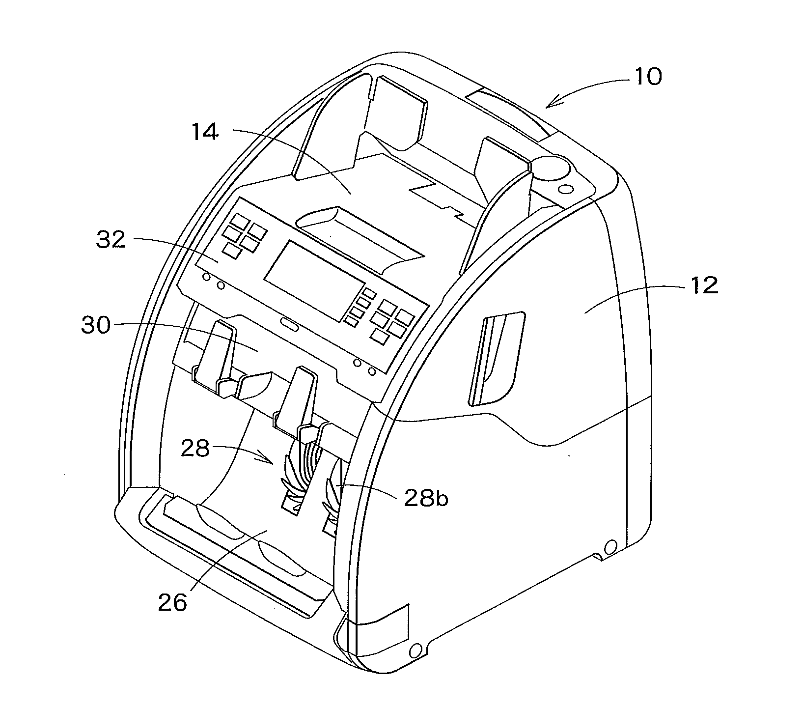
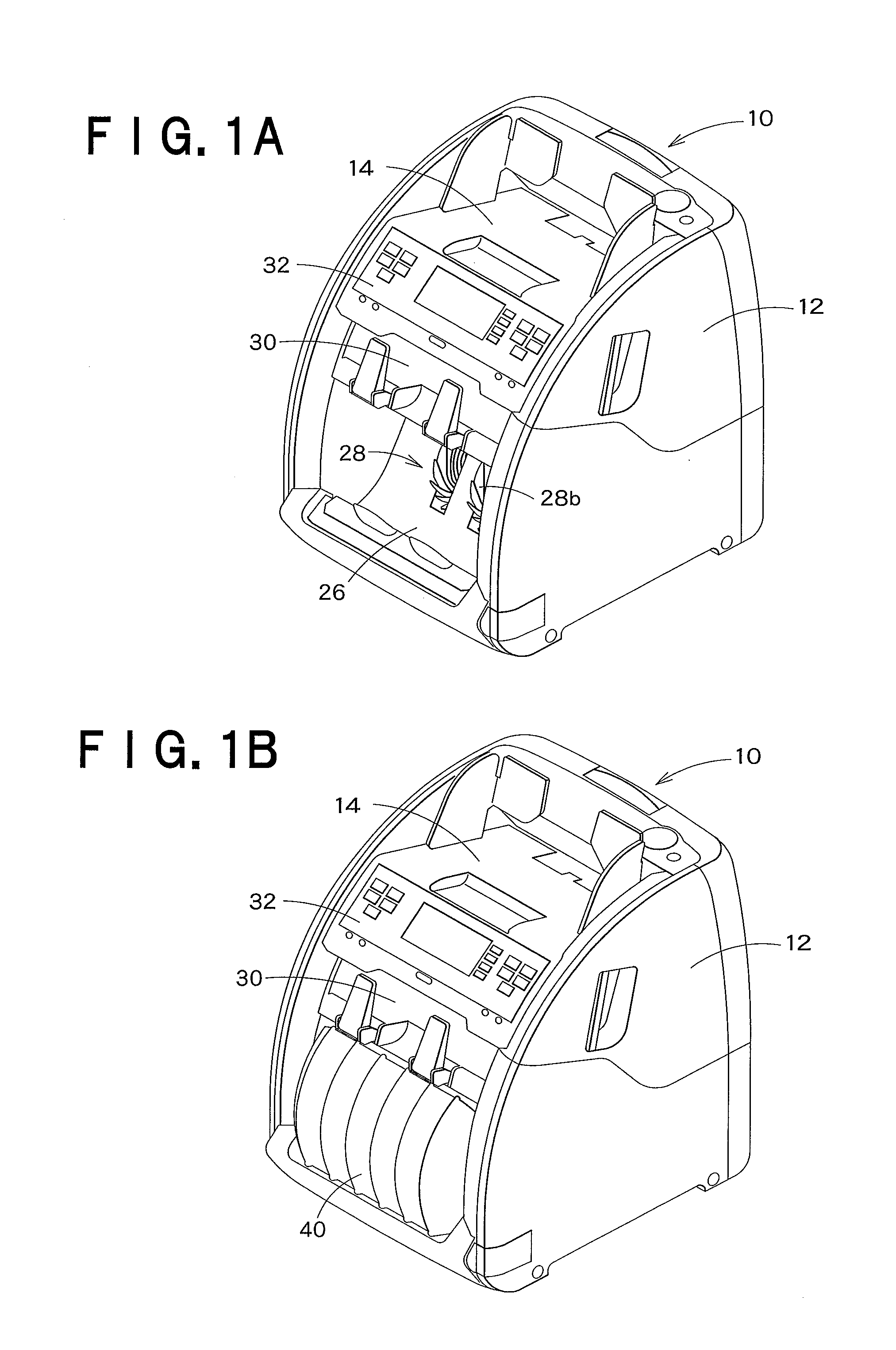
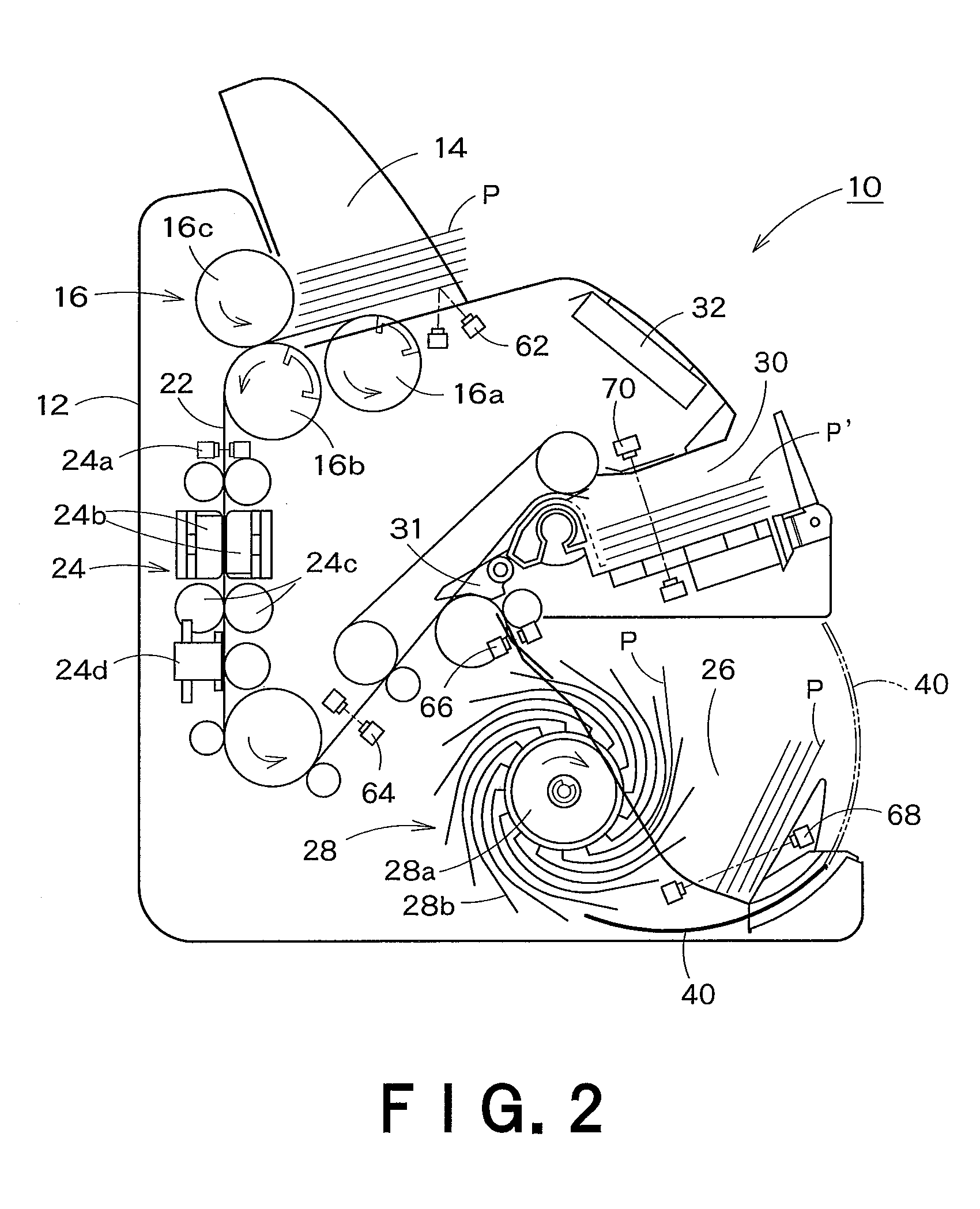
[0046]Hereinafter, one embodiment of the present invention will be described, with reference to the drawings. As used herein, FIGS. 1 through 12 are provided for respectively illustrating the banknote recognition and counting machine related to the embodiment. Of these drawings, FIGS. 1A and 1B respectively illustrate one perspective view of the banknote recognition and counting machine related to this embodiment. FIG. 2 schematically illustrates the internal construction of the banknote recognition and counting machine shown in FIGS. 1A and 1B, and FIG. 3 illustrates the details of the operation / display unit of the banknote recognition and counting machine shown in FIG. 1 and so on. FIG. 4 illustrates one exemplary control system of the banknote recognition and counting machine shown in FIG. 1 and so on. The side view of FIG. 5 schematically illustrates the construction of the recognition and counting unit provided in the banknote recognition and counting machine shown in FIG. 2. F...


PUM


Abstract

Banknotes are taken into a banknote recognition and counting machine (10), a recognition and counting process for the banknotes is performed by a recognition and counting unit (24), judgment for the banknotes is performed by using a first judgment threshold value, based on the recognition result on each banknote recognized by the recognition and counting unit (24), and then the banknotes are fed, selectively, to a stacking unit (26) or reject unit (30), based on the judgment result on each banknote. Then the banknotes, respectively fed to the reject unit (30), are taken again into the banknote recognition and counting machine (10), the recognition and counting process for such banknotes is performed by the recognition and counting unit (24), and then the judgment for the banknotes is performed, by using a second judgment threshold value set smaller than the first judgment threshold value, based on the recognition result on each banknote recognized by the recognition and counting unit (24). Thereafter, information, which relates to the total sum of a count result on the banknotes, respectively judged to be true upon the judgment for the banknotes by using the first judgment threshold value and another count result on the banknotes, respectively judged to be true upon the judgment for the banknotes by using the second judgment threshold value, is output.

Description

FIELD OF THE INVENTION[0001]The present invention relates to a banknote recognition and counting machine and a banknote recognition and counting method, respectively adapted for recognizing and counting banknotes.BACKGROUND ART[0002]In the past, various types of machines have been used as the banknote recognition and counting machine adapted for recognizing and counting the banknotes. In general, the banknote recognition and counting machine includes a placing unit adapted for placing thereon the banknotes and feeding such placed banknotes, one by one, into a casing, a recognition and counting unit provided in the casing and adapted for recognizing and counting the banknotes respectively fed into the casing from the placing unit, and a stacking unit adapted for stacking therein the banknotes after such banknotes are recognized and counted by the recognition and counting unit and then fed to the stacking unit. Further, this banknote recognition and counting machine includes a reject ...

Claims


Application Information

Patent Timeline
IPC IPC(8): G06K15/02G06F7/00G07D7/00G06M3/06G07F7/04G06M3/00
CPCG07D11/0084G07D7/00G07D7/04G07D7/12G07D11/50G07D11/10
Inventor MATSUURA, SHINJIMORINO, HAJIME
Owner GLORY KOGYO KK
Why Eureka
Try Eureka