
Imaging apparatus and imaging method

Inactive Publication Date: 2008-10-09
SONY CORP
View PDF2 Cites 11 Cited by
  • Summary
  • Abstract
  • Description
  • Claims
  • Application Information

AI Technical Summary

Benefits of technology

[0018]According to the embodiment of the invention, a person who performs an imaging operation may only select any of optical filters, such as an ND filter. Usual imaging has no need to set color temperature, so that the setting operation for imaging can be carried out readily. For example, when the photographer moves outdoors from a dark room while imaging, an appropriate ND filter is selected after moving from the environment without the use of an ND filter. In this case, color temperature can be automatically set to one suitable for outdoor imaging from one suitable for indoor imaging, thereby simplifying the imaging operation.

Problems solved by technology

In the case of externally mounting a separate ND filter, the filter can be manually attached and removed by the user and such works can be time-consuming.

Method used


Image

  • Imaging apparatus and imaging method
  • Imaging apparatus and imaging method
  • Imaging apparatus and imaging method

Examples


Embodiment Construction

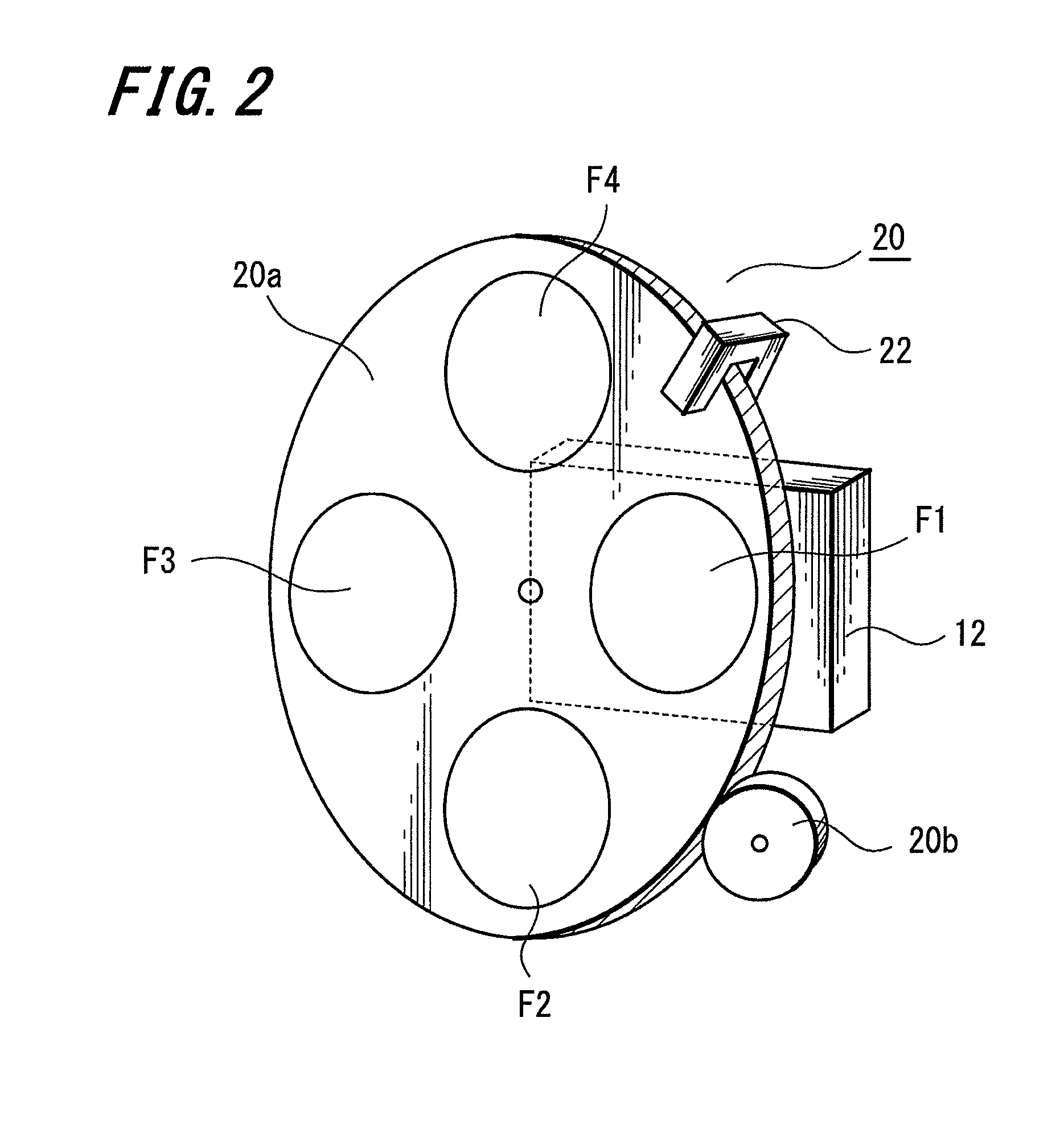
[0025]Hereinafter, an embodiment of the invention will be described with reference to FIGS. 1 to 6.

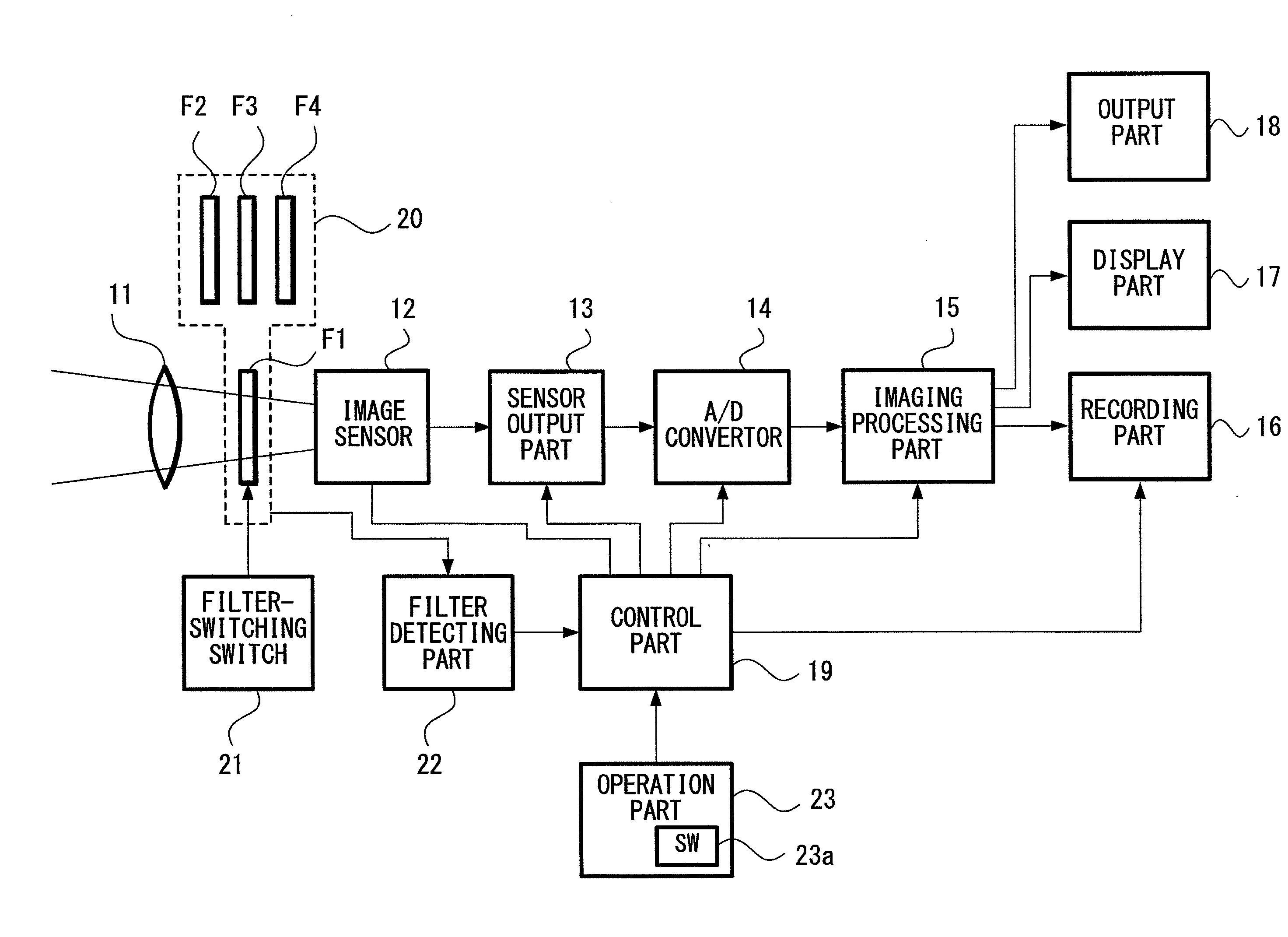
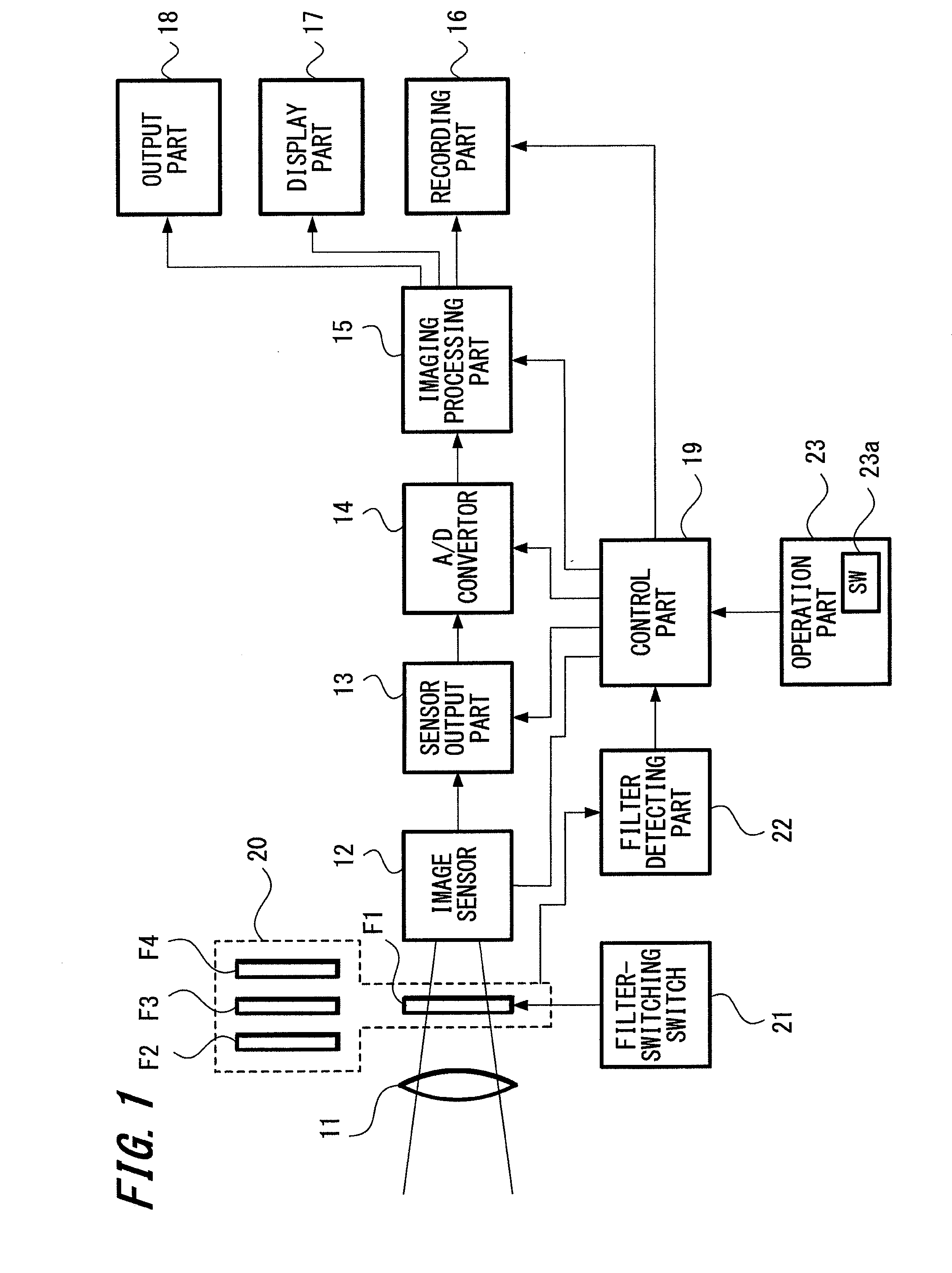
[0026]FIG. 1 is a block diagram showing a configuration of an imaging apparatus according to the embodiment of the invention. The configuration of the imaging apparatus will be described with reference to FIG. 1. Imaging light passing through a lens 11 forms an image on the imaging surface of an image sensor 12. The imaging light is then converted into an electric signal at the image sensor 12. Subsequently, a sensor output part 13 reads the converted electric signal. The electric signal read at the sensor output part 13 is referred to as an imaging signal.

[0027]As shown in FIG. 1, the lens 11 is represented as a single lens for simplifying the description thereof. In fact, however, the lens 11 is formed of a plurality of lenses (a plurality of lens groups) and may be provided as a zoom lens. Furthermore, although not shown in the figure, an iris or a diaphragm mechanism is arranged in...


PUM


Abstract

An imaging apparatus includes one or a plurality of optical filters, an image sensor, an imaging signal processing part, a detecting part, and a control part. The one or the plurality of optical filters are selectively arranged in a path of an optical system for obtaining imaging light. The image sensor is provided for converting the imaging light obtained through the optical system into an imaging signal. The imaging signal processing part is provided for subjecting the imaging signal from the image sensor to a color-temperature correction processing. The detecting part is provided for detecting a type of the one or the plurality of optical filters arranged in the optical system. The control part is provided for adjusting a color temperature that is set at the imaging signal processing part to a color temperature defined for each filer detected by the detecting part.

Description

CROSS REFERENCE TO RELATED APPLICATIONS[0001]The present invention contains subject matter related to Japanese Patent Application 2007-097593 filed in the Japanese Patent Office on Apr. 3, 2007, the entire contents of which being incorporated herein by reference.BACKGROUND OF THE INVENTION[0002]1. Field of the Invention[0003]The invention relates to an imaging apparatus applied to a video camera in which an optical filter, such as an ND filter, can be selectively arranged. The invention also relates to an imaging method applied in such an imaging apparatus, particularly relating to color-temperature setup technology.[0004]2. Description of the Related Art[0005]Capturing an image using a video camera may require the setting of appropriate color temperature, which can be provided as the basis for an imaging signal. The phrase “setting of color temperature” means that, for example, when capturing an image of a white subject, color temperature is adjusted (corrected) for allowing the wh...

Claims


Application Information

Patent Timeline
IPC IPC(8): H04N9/73G03B7/28G03B11/00H04N5/232H04N9/04
CPCH04N9/045H04N9/735H04N23/631H04N23/88
Inventor SHIBUYA, KAZUAKINAKAMARU, HIDEKI
Owner SONY CORP
Learn More