Regulated fluid dispensing system packaging

Inactive Publication Date: 2009-11-19
MILLERCOORS
70 Cites 8 Cited by

AI-Extracted Technical Summary

Problems solved by technology

For larger bulk containers of beverages, such as kegs of beer, because of their size and the nature of the kegs, it is usually unnecessary to provide separate packagi...

Benefits of technology

[0006]In accordance with the present invention, a packaging container or carton is provided that is especially adapted for housing a fluid dispensing system wherein the packaging container can be used to ship and store the system, as well as to allow the system to remain protected within the packaging during use. As discussed in more detail below, the packaging container includes a front panel that may be completely removed, thereby exposing the dispensing tap of the fluid dispensing system. The fluid dispensing system including the attached beverage container can remain within the packaging container, thereby providing a stable support for the bever...

Abstract

A packaging container is used to package a regulated fluid dispensing system including a regulated fluid dispensing device and a beverage container. The packaging includes carry handles, and a perforation pattern that allows a front panel of the packaging container to be removed thus exposing working parts of the dispensing device. The dispensing system may remain housed within the packaging during use that assists in stabilizing and protecting the dispensing system.

Application Domain

Technology Topic

Biomedical engineeringMaterial Perforation

Image

  • Regulated fluid dispensing system packaging
  • Regulated fluid dispensing system packaging
  • Regulated fluid dispensing system packaging

Examples

  • Experimental program(1)

Example

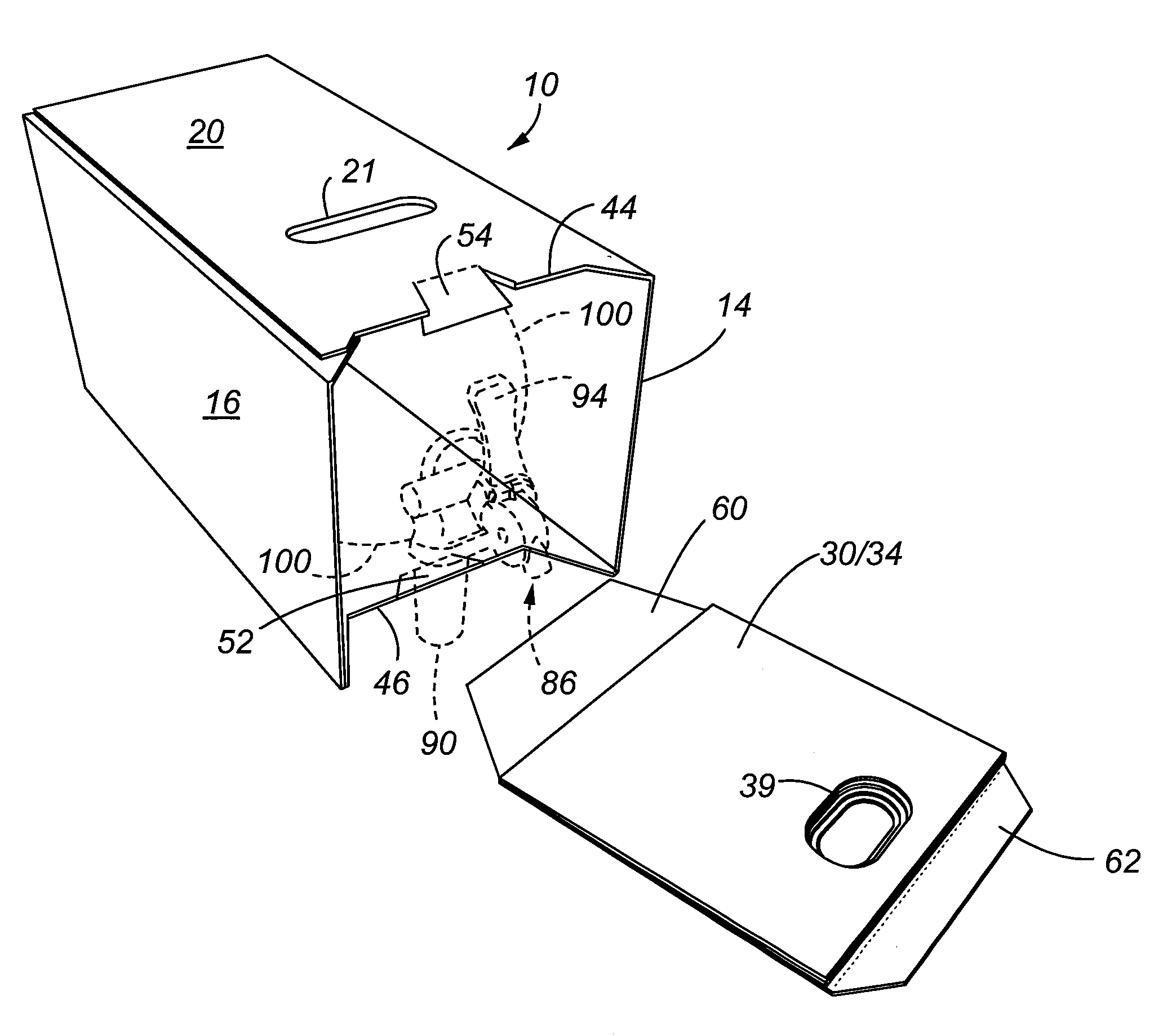
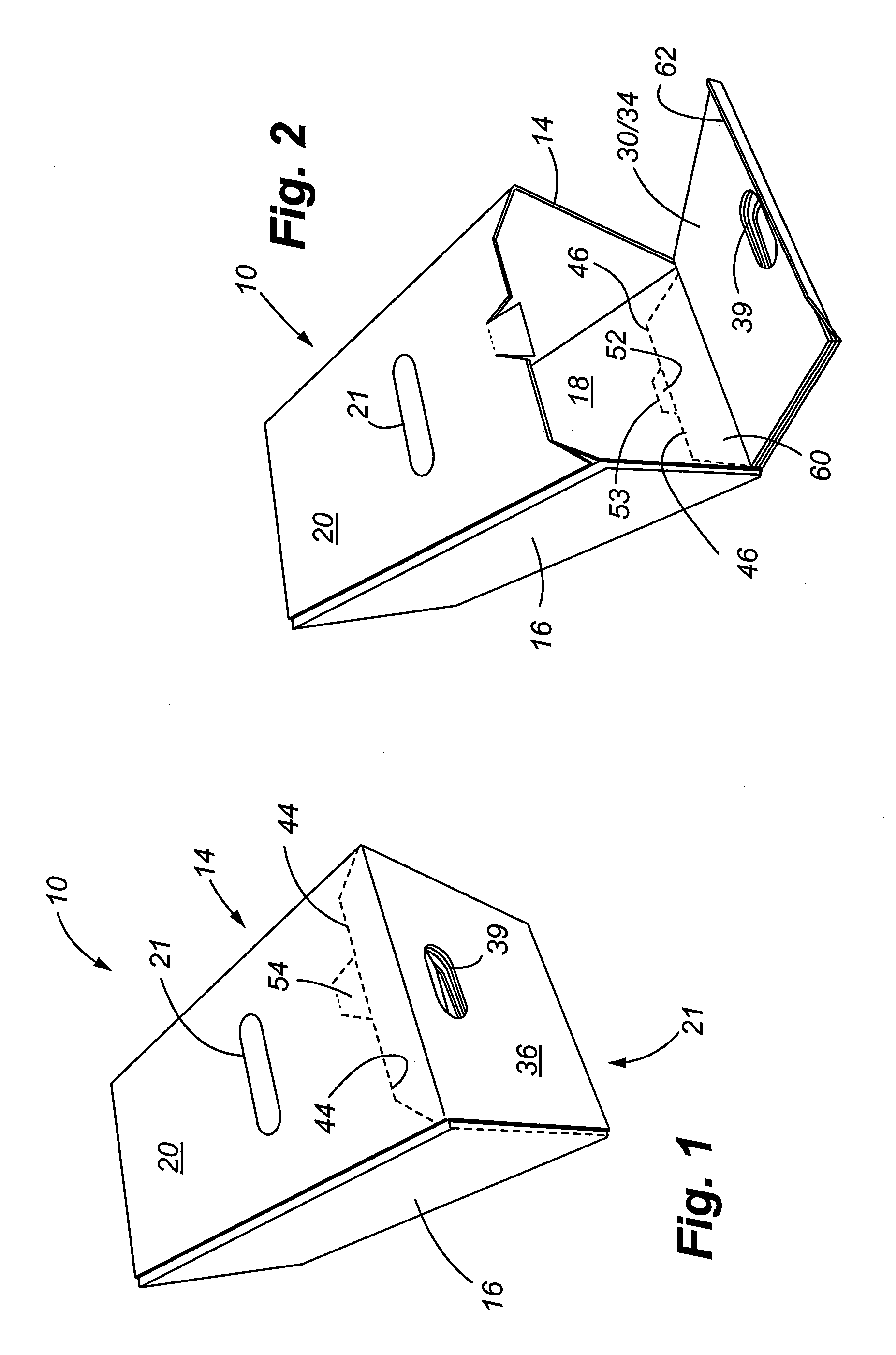
[0014]Referring to FIGS. 1 and 2, the packaging container 10 of the present invention is illustrated. The exterior surface of the packaging is defined by an outer top panel 20, an opposed bottom panel 18, and an opposed pair of side panels, shown as first side panel 14 and second side panel 16.
[0015]Referring also to FIG. 5, the plan view of the packaging container 10 illustrates each of the panels and flaps of the packaging container prior to assembly of the packaging. Referring specifically to this FIG. 5, the packaging 10 further includes an inner top panel 12, which resides under the outer top panel 20 when the packaging is assembled. Slot 13 of the inner panel 12 aligns with the slot 21 formed on the outer top panel 20 to form a top carry opening. The back or rear panel of the packaging includes a plurality of closing flaps, namely, a first rear side closing flap 22, a rear bottom closing flap 24, a second rear side closing flap 26, and a top rear closing flap 28. When the packaging is assembled, the closing flaps close the rear side of the package in a conventional manner wherein pairs of opposing flaps are rotated to close the rear side. The front panel 21 of the packaging also includes a plurality of closing flaps to include first front side closing flap 30, front bottom closing flap 32, second front side closing flap 34, and the front closing flap 36. Top front closing flap 36 includes a top front carry opening 39. Each of the front closing flaps includes corresponding slots that form the front carry opening 39, well as a means to remove the front panel as discussed further below. These slots include first side slot 31, bottom slot 33, second side slot 35, and top slot 37. When the packaging is folded, the slots 31, 33, 35 and 37 align with one another as shown in FIGS. 1 and 2 to form the front carry opening 39.
[0016]FIG. 5 illustrates further details to include the various fold lines 56 and 58 that allow the packaging to be folded in the configuration shown in the figures. As shown, the fold lines delineate the separation between the various panels and flaps. FIG. 5 also illustrates other features of the packaging container to include various perforation lines that delineate additional flaps. More specifically, bottom panel 18 includes perforation line 46 that delineates a bottom breakaway flap 60. A bottom hand pull-tab 52 is defined by (i) a portion of perforation line 46, (ii) fold 53 that is spaced from perforation line 46, and (iii) perforation lines 59 that interconnects fold 53 with perforation line 46. The outer top panel 20 also includes a top breakaway flap 62 defined by perforation line 44. A top hand pull-tab 54 is formed on the top panel 20 as is defined by (i) a portion of perforation line 44, (ii) fold line 57, and (iii) the pair of interconnection perforation lines 55.
[0017]Referring to FIGS. 2 and 4, when it is desired to access the interior of the packaging container, the user breaks the portion of the perforation line 44 located at the hand tab 54, and breaks the interconnecting perforations 55 that therefore allow the hand to be inserted within the container. The user can then pull forward on the front panel, thereby separating the front panel such that the interior of the packaging is exposed. As shown in FIG. 2, the breakaway flap 62, when separated from the top panel, forms a slot or notch in the top panel.
[0018]Referring to FIG. 5, the inner top panel 12 has a corresponding cutout 40, as well as a slot 50 that underlie the breakaway flap 62. As shown in FIG. 4, if it is desired to completely remove the front panel, the user may break the perforation line 46 at bottom tab 52, and then pull such that the breakaway flap 60 is removed from the bottom panel 18.
[0019]Referring to FIG. 3, an exemplary regulated fluid dispensing system is shown including a beverage container 100 having a cylindrical sidewall, which is connected to a regulated fluid dispensing device 80. The fluid dispensing device 80 generally includes a regulator housing 82, an outlet housing 84, an outlet 86, and an outlet tube 88 that carries the beverage to the outlet. A cartridge housing 90 attaches to the regulator housing 82. The cartridge housing 90 houses a cartridge (not shown) containing a compressed gas, which is used to pressurize the beverage container 100. A connection housing 92 interconnects a threaded neck 102 of the beverage container to the dispensing device 80. A tap handle 94 is used to control the flow of beverage. An inlet tube 104 is used to draw the beverage through the dispensing device to the outlet tube 88. A weighted tip 106 defines the distal or free end of the inlet tube 104. Optionally, a plurality of feet 108 may be made integral with the beverage container sidewall, allowing a more stable surface for the beverage container to rest upon when the dispensing device is in use.
[0020]Referring specifically to FIG. 4, the fluid dispensing device 80 and beverage container 100 are shown within the packaging container 10. The dispensing device 80 is exposed allowing a user to conveniently access the working parts of the dispensing device 80. More particularly, the breakaway flaps 60 and 62 when removed from the packaging create gaps that more easily allow the user to gain access to the working parts, such as the tap handle 94, and the cartridge housing 90. Periodically, the compressed gas cartridge must be replaced by unscrewing the cartridge housing and placing a new cartridge in the housing. As shown in FIG. 4, the packaging provides additional support to the dispensing device and beverage container such that the dispensing device and beverage container may be conveniently stored on a horizontal surface such as a shelf.
[0021]FIG. 6 illustrates an optional partition 110 that may be used to further stabilize the container within the packaging. As shown, the partition 110 extends across the front portion of the container and a slot 112 allows the fluid dispensing device to remain exposed, while the container is hidden on the opposite side of the partition. Accordingly, the slot 112 is formed to surround the neck of the container. The partition 110 includes a pair of side contacting flaps 116 that make contact with respective interior sidewalls of the container. Folds 114 can be positioned so that the partition 110 fits snuggly within the interior of the packaging.
[0022]By the foregoing, packaging is provided for a regulated fluid dispensing device and beverage container wherein the packaging conveniently allows for transport and storage, as well as use of the dispensing device without having to remove the dispensing device from within the packaging. The removable front panel enables access to the interior of the packaging, and to the various working parts of the dispensing device without destroying the basic integrity of the packaging.
[0023]Although the foregoing invention has been disclosed with respect to preferred embodiments, it shall be understood that various other changes and modifications can be made commensurate with the scope of the claims appended hereto.

PUM

no PUM

Description & Claims & Application Information

We can also present the details of the Description, Claims and Application information to help users get a comprehensive understanding of the technical details of the patent, such as background art, summary of invention, brief description of drawings, description of embodiments, and other original content. On the other hand, users can also determine the specific scope of protection of the technology through the list of claims; as well as understand the changes in the life cycle of the technology with the presentation of the patent timeline. Login to view more.

Similar technology patents

Classification and recommendation of technical efficacy words

  • Stably support
  • Easily grasp

Lumbar support seat

InactiveUS20130043707A1Stably supportPrevent stressStuffed mattressesChiropractic devicesVertebraEngineering
Owner:YOON WOOK
Why Eureka
Try Eureka