
Handrail for preventing stairway falls

Inactive Publication Date: 2011-02-24
ANDERSON JOHN S
View PDF9 Cites 2 Cited by
  • Summary
  • Abstract
  • Description
  • Claims
  • Application Information

AI Technical Summary

Benefits of technology

[0013]There has been summarized above, rather broadly, the prior art that is related to the present invention in order that the context of the present invention may be better understood and appreciated. In this regard, it is instructive to briefly consider the objects and advantages of the present invention.
[0014]It is an object of the present invention to provide an improved handrail whose use will make it safer for the elderly and others (e.g., those with ambulatory infirmities, poor vision or balance problems) to ascend or descend stairs.
[0015]It is an object of the present invention to provide a low-cost way to modify an otherwise conventional pole-like handrail so that this modified handrail's use will make it safer for the elderly and others (e.g., those with ambulatory infirmities, poor vision or balance problems) to ascend or descend stairs.
[0016]It is an object of the present invention to provide a low-cost way to retrofit existing pole-like handrails so that such a retrofitted handrail's use will make it safer for the elderly and others (e.g., those with ambulatory infirmities, poor vision or balance problems) to ascend or descend stairs.
[0017]It is an object of the present invention to modify or retrofit an otherwise conventional pole-like h

Problems solved by technology

If for any reason the person should, during the ascent or descent of the stairs, let go of the handrail and try to pull his or her hand away from the handrail—one would not be able to do so since such an action would tend to pull the member up through the slot and cause the spacer to contact the top of the bore where it cannot pass through the handrail's slot and where friction between the spacer and the bore's top surface will prevent the wrist band from being moved further up or down the stair.

Method used


Image

  • Handrail for preventing stairway falls
  • Handrail for preventing stairway falls
  • Handrail for preventing stairway falls

Examples


Embodiment Construction

[0030]Before explaining at least one embodiment of the present invention in detail, it is to be understood that the invention is not limited in its application to the details of construction and to the arrangements of the components set forth in the following description or illustrated in the drawings. The invention is capable of other embodiments and of being practiced and carried out in various ways. Also, it is to be understood that the phraseology and terminology employed herein are for the purpose of description and should not be regarded as limiting.

[0031]The present invention, in the form of a safer handrail, reduces the risk of one who uses such a handrail from falling when ascending or descending the stairway that the handrail serves.

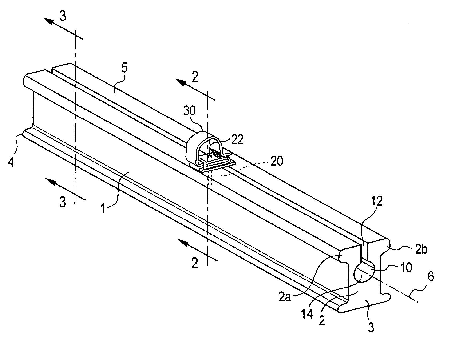
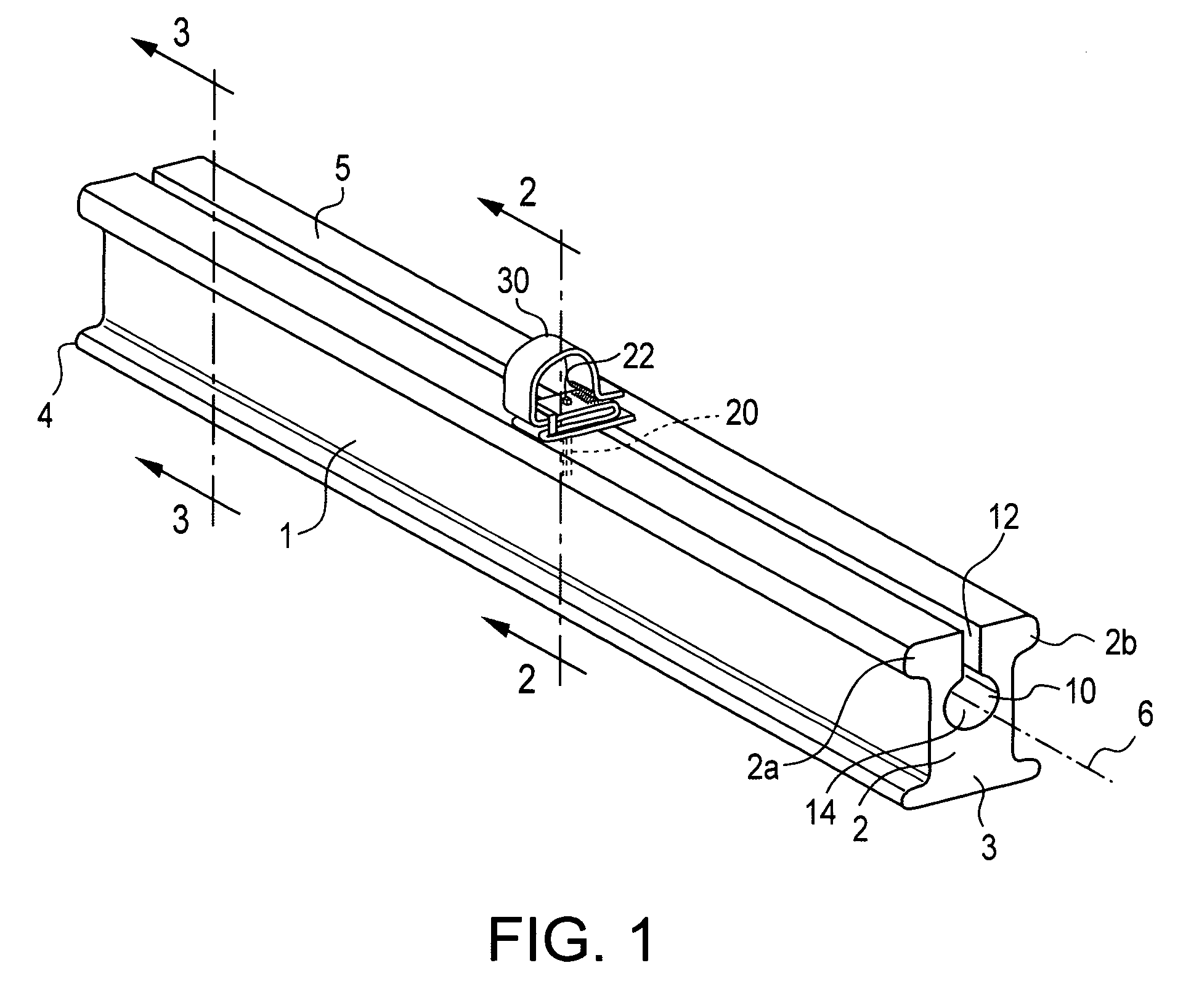
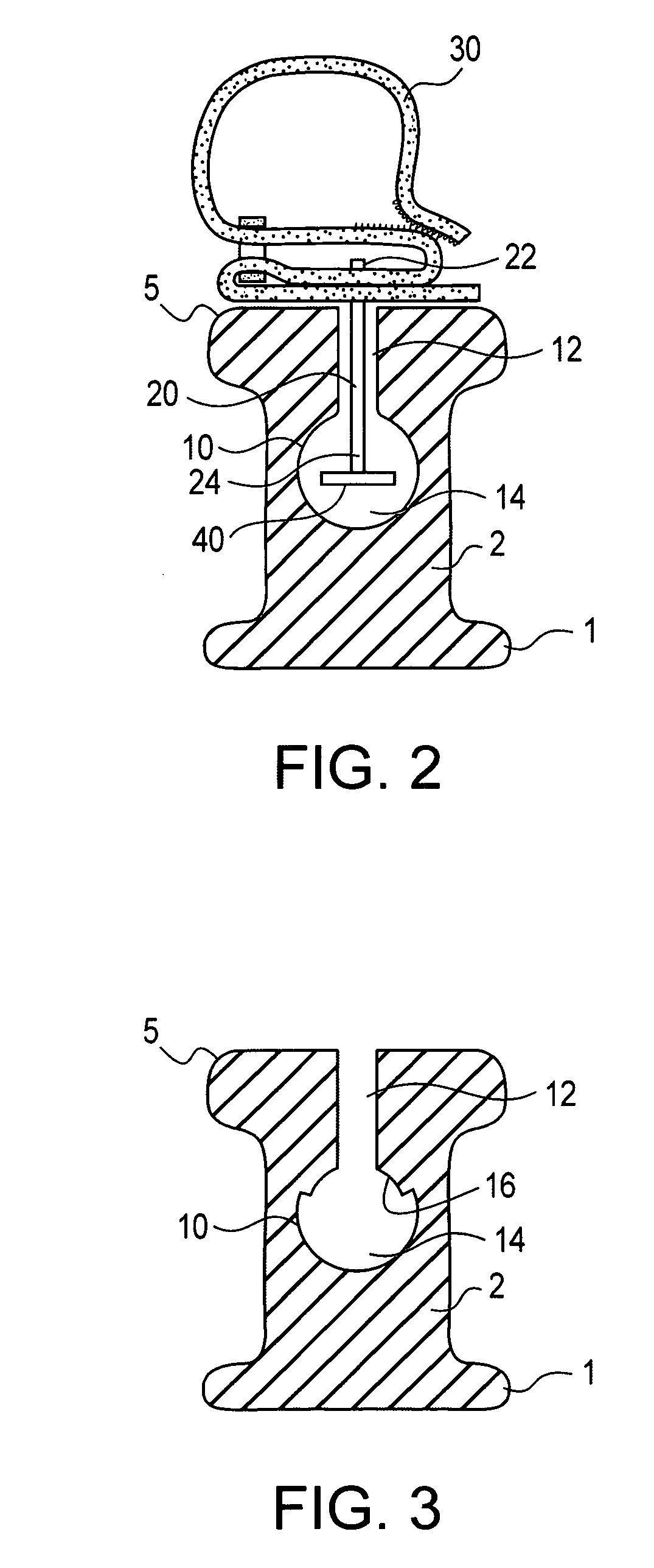
[0032]FIG. 1 shows a first preferred embodiment of a modified version of an otherwise conventional, pole-like handrail. It is seen to be a handrail 1 which has a relatively conventional looking exterior surface that includes a symmetrical-about...


PUM

PropertyMeasurementUnit
Widthaaaaaaaaaa
Distanceaaaaaaaaaa

Abstract

To further prevent stairway falls, an otherwise conventional handrail, of the type that is mounted on the sidewall of a stairway and has an upper portion which is configured to be easily grasped by one utilizing, is modified by providing it with a two-part cavity in the interior of the handrail, with its first part being a slot that extends from the handrails' exterior surface and its second part being a bore that is situated in the handrail's interior and joined with the slot so as to make the bore accessible from the handrail's exterior surface. This modified handrail is also to provided with a wrist securing device that works in cooperation with the handrail's cavity for keeping the wrist of a user in close proximity to the handrail when the user is traversing the stairway.

Description

CROSS-REFERENCE TO RELATED APPLICATION[0001]This application is a continuation-in-part of the pending patent application U.S. Ser. No. 11 / 998,633—filed Nov. 30, 2007. The teachings of this prior patent application are incorporated by reference herein and to the extent that they do not conflict with the teachings of the present application.BACKGROUND OF THE INVENTION[0002]1. Field of the Invention[0003]The present invention relates generally to static structures and the handrails found therein, and, in particular, to a handrail adjoining a stair that is configured to minimize the risk of one falling on the stairs.[0004]2. Description of the Related Art[0005]Handrails are well known parts of multi-story buildings that are primarily used for the purpose of trying to prevent a person from falling when ascending or descending a stairway.[0006]However, despite the use of handrails, each year thousands of people die and tens of thousands are injured from falls on stairways in their homes a...

Claims


Application Information

Patent Timeline
IPC IPC(8): E04H17/14B23P17/00
CPCA61H2003/001Y10T29/49716E04F11/1863B66B23/22
Inventor ANDERSON, JOHN S.
Owner ANDERSON JOHN S
Learn More