Monitoring system

Pending Publication Date: 2020-06-11
JUKI CORP
View PDF6 Cites 1 Cited by
  • Summary
  • Abstract
  • Description
  • Claims
  • Application Information

AI Technical Summary

Benefits of technology

[0017]According to the present invention, the status of the entire floor can be easily grasped by recognizing the m

Problems solved by technology

In addition, a trouble occurring in the line until the manufactured article is completed is written on the ID plate and used as analysis data.
However, in the system describ

Method used


Image

  • Monitoring system
  • Monitoring system
  • Monitoring system

Examples


Example

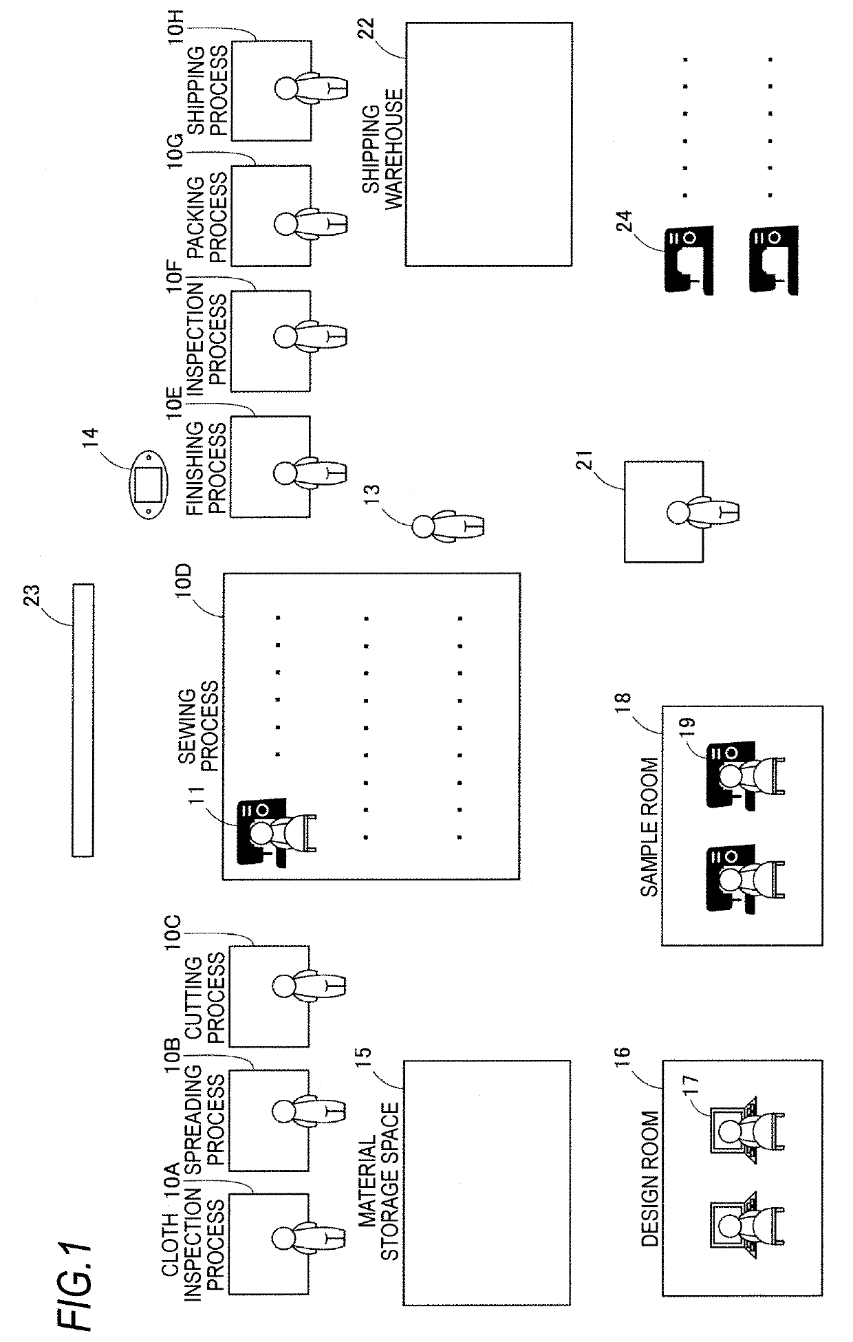
[0025]Hereinafter, a sewing factory that employs a monitoring system according to an embodiment of the present invention will be described with reference to the accompanying drawings. FIG. 1 is an overall schematic diagram of the sewing factory according to the embodiment. The monitoring system according to the embodiment is not limited to a sewing factory where clothing is manufactured, and may be applied to various facilities ranging from a small-scale work place to a large-scale factory.

[0026]As illustrated in FIG. 1, on the floor of a sewing factory, a manufacturing line is constructed by a cloth inspection process, a spreading process, a cutting process, a sewing process, a finishing process, an inspection process, a packing process, and a shipping process. A product such as clothing is manufactured by bringing a material into the manufacturing line and performing various processing on the material in each process. In each process, various manufacturing equipment 10 is installe...


PUM


Abstract

The present embodiment provide a monitoring system for monitoring at least one of fixed equipment installed in a floor and a moving object moving in the floor, the fixed equipment and moving object being monitoring targets, the monitoring system includes a recognition device that recognizes the monitoring target and outputs recognition information, and a management device that collects position information of the monitoring target from the recognition information.

Description

CROSS-REFERENCE TO RELATED APPLICATIONS[0001]The present application claims the benefit of priority of Japanese Patent Application No. 2018-228157, filed on Dec. 5, 2018, the content of which is incorporated herein by reference.TECHNICAL FIELD[0002]The present invention relates to a monitoring system for monitoring a monitoring target in a floor.BACKGROUND ART[0003]In the related art, a system for monitoring a status of a manufactured article in each process of a manufacturing line has been proposed (see, for example, JP-A-1992-283058). In the system described in JP-A-1992-283058, an ID plate is attached to the manufactured article or an automated guided vehicle on which the manufactured article is placed and appropriate processing is performed on the manufactured article using the ID plate in each process. For example, a processing content in each process is stored in the ID plate, and the processing content for the manufactured article is recognized by using the processing content...

Claims


Application Information

Patent Timeline
IPC IPC(8): G05B19/4063
CPCG05B2219/45195G05B2219/32286G05B19/4063G05B19/4183D05B19/00G05B19/41875G06Q50/04G06Q10/0631G06Q10/0833Y02P90/02Y02P90/30
Inventor ATSUMI, TADASHI
Owner JUKI CORP
Why Eureka
Try Eureka