Wing tip joint in airfoils

a technology of airfoil and wing tip, which is applied in the field of aircraft structure components and wing tip joints in airfoils, can solve the problems of reducing the amount of room available for structural components within the airfoil, wing tips at the ends of the wing may require repairs or replacement, and the thickness or cross section of the airfoil is too larg

Active Publication Date: 2009-11-19
THE BOEING CO
View PDF12 Cites 53 Cited by
  • Summary
  • Abstract
  • Description
  • Claims
  • Application Information

AI Technical Summary

Problems solved by technology

The reduction in the thickness or cross section of the airfoil also reduces the amount of room available for structural components within the airfoil.
Also, the ...

Method used


Image

  • Wing tip joint in airfoils
  • Wing tip joint in airfoils
  • Wing tip joint in airfoils

Examples


Embodiment Construction

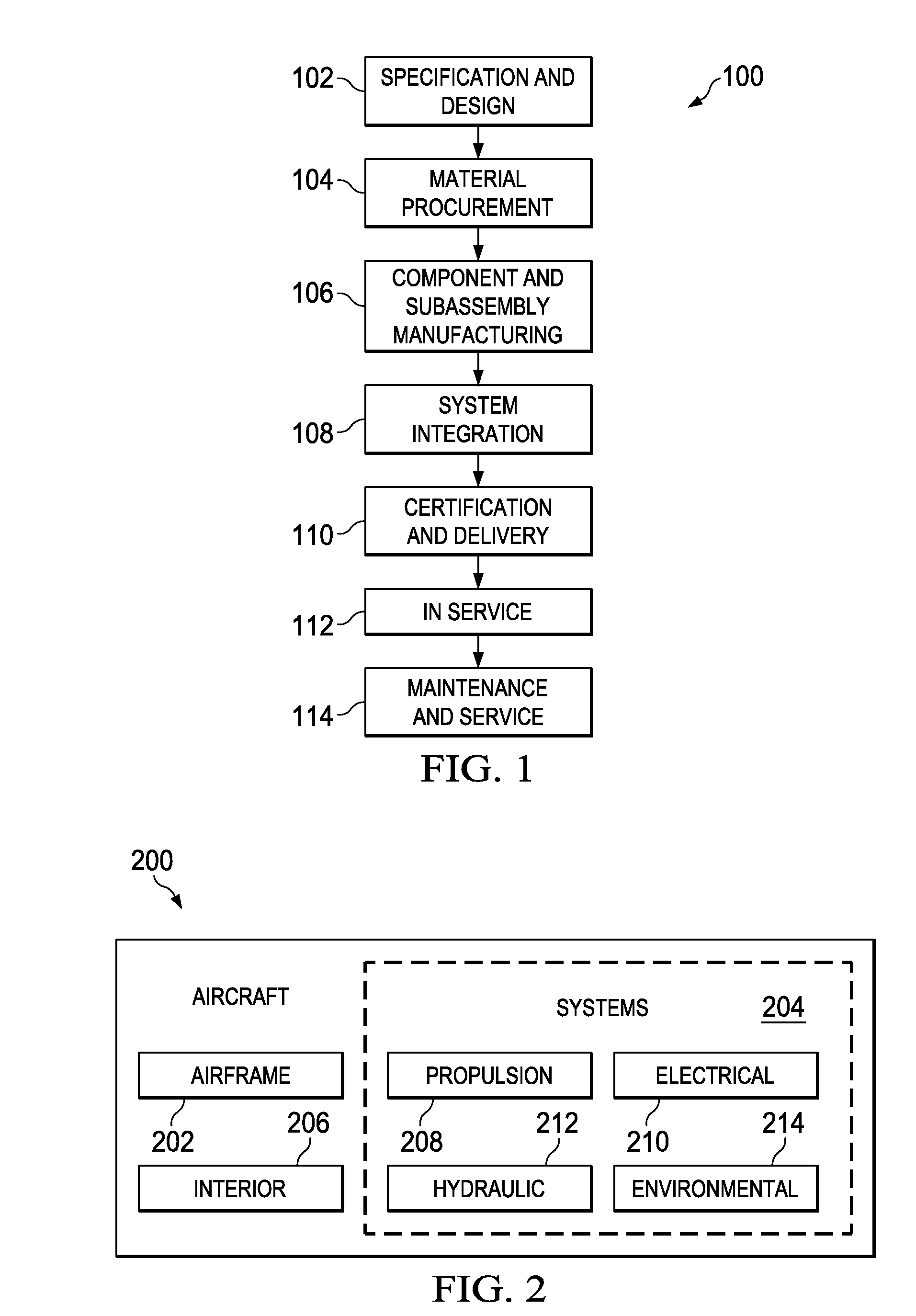
[0029]Referring more particularly to the drawings, embodiments of the disclosure may be described in the context of the aircraft manufacturing and service method 100 as shown in FIG. 1 and aircraft 200 as shown in FIG. 2. Turning first to FIG. 1, a diagram illustrating an aircraft manufacturing and service method is depicted in accordance with an advantageous embodiment. During pre-production, exemplary aircraft manufacturing and service method 100 may include specification and design 102 of aircraft 200 in FIG. 2 and material procurement 104.

[0030]During production, component and subassembly manufacturing 106 and system integration 108 of aircraft 200 in FIG. 2 takes place. Thereafter, aircraft 200 in FIG. 2 may go through certification and delivery 110 in order to be placed in service 112. While in service by a customer, aircraft 200 in FIG. 2 is scheduled for routine maintenance and service 114, which may include modification, reconfiguration, refurbishment, and other maintenance...


PUM


Abstract

An aircraft joint comprises a wing structure and a wing tip. The wing structure has a first part of a clevis and lug fastening system located around an outer end of the wing structure. The wing tip has a second part of the clevis and lug fastening system located around an end of the wing tip. The wing tip is capable of being joined to the outer end of the wing structure. An upper aerodynamic surface and a lower aerodynamic surface are formed by joining the wing structure and the wing tip. The first part and the second part are located about a center between the upper aerodynamic surface and the lower aerodynamic surface. The first part and the second part engage each other such that a moment reaction occurs around the upper aerodynamic surface and the lower aerodynamic surface.

Description

BACKGROUND INFORMATION[0001]1. Field:[0002]The present disclosure relates generally to aircraft and in particular to structural components in aircraft. Still more particularly, the present disclosure relates to a method and apparatus for a wing tip joint in an airfoil.[0003]2. Background:[0004]An airfoil is a shape of an aerodynamic structure, such as a wing, a blade, or a sail. The airfoil may be a cross sectional shape of the aerodynamic structure. The airfoil shape of a wing of an aircraft when moved through air produces a force perpendicular to the motion called lift. Typically, an airfoil may have a round leading edge followed by a sharp trailing edge.[0005]In marketing aircraft, performance is an important parameter or factors. One manner in which performance may be increased is through making the shape of an airfoil thinner. The reduction in the thickness of an airfoil results in less aerodynamic drag.[0006]The reduction in the thickness or cross section of the airfoil also r...

Claims


Application Information

Patent Timeline
IPC IPC(8): B64C3/18
CPCB64C3/18Y02T50/164B64C23/065B64C3/26B64C23/069Y02T50/10
Inventor ACKERMANN, JAMES F.TANNER, RICHARD B.
Owner THE BOEING CO
Why Eureka
Try Eureka