

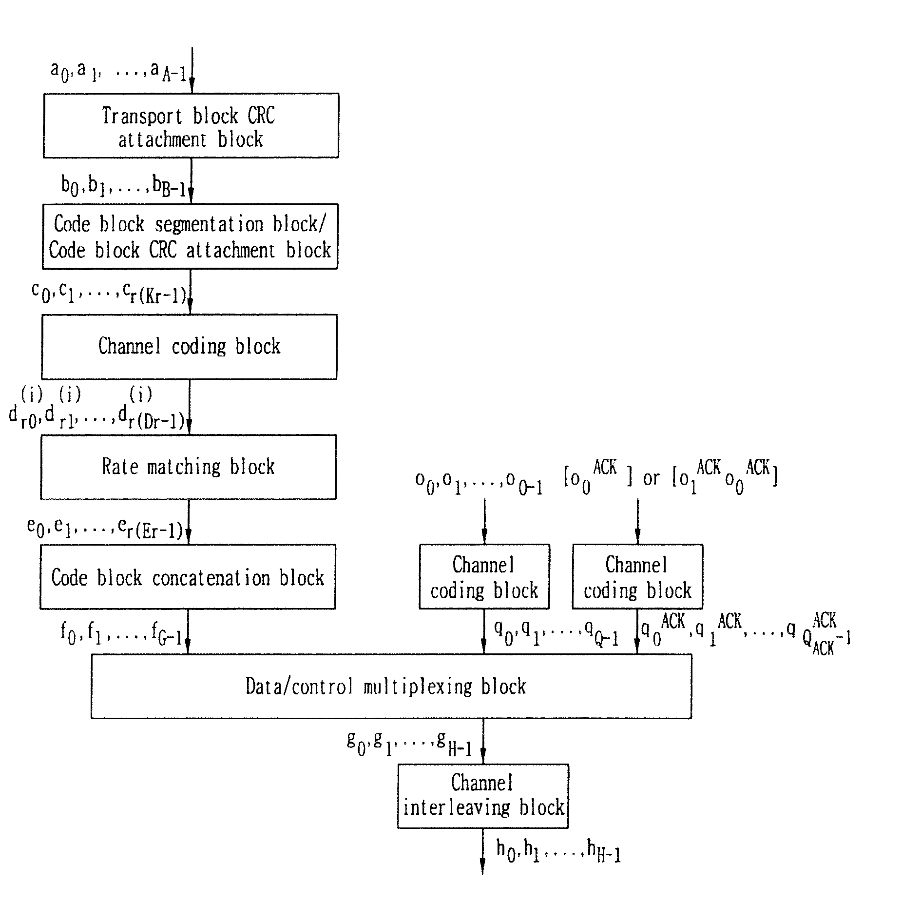
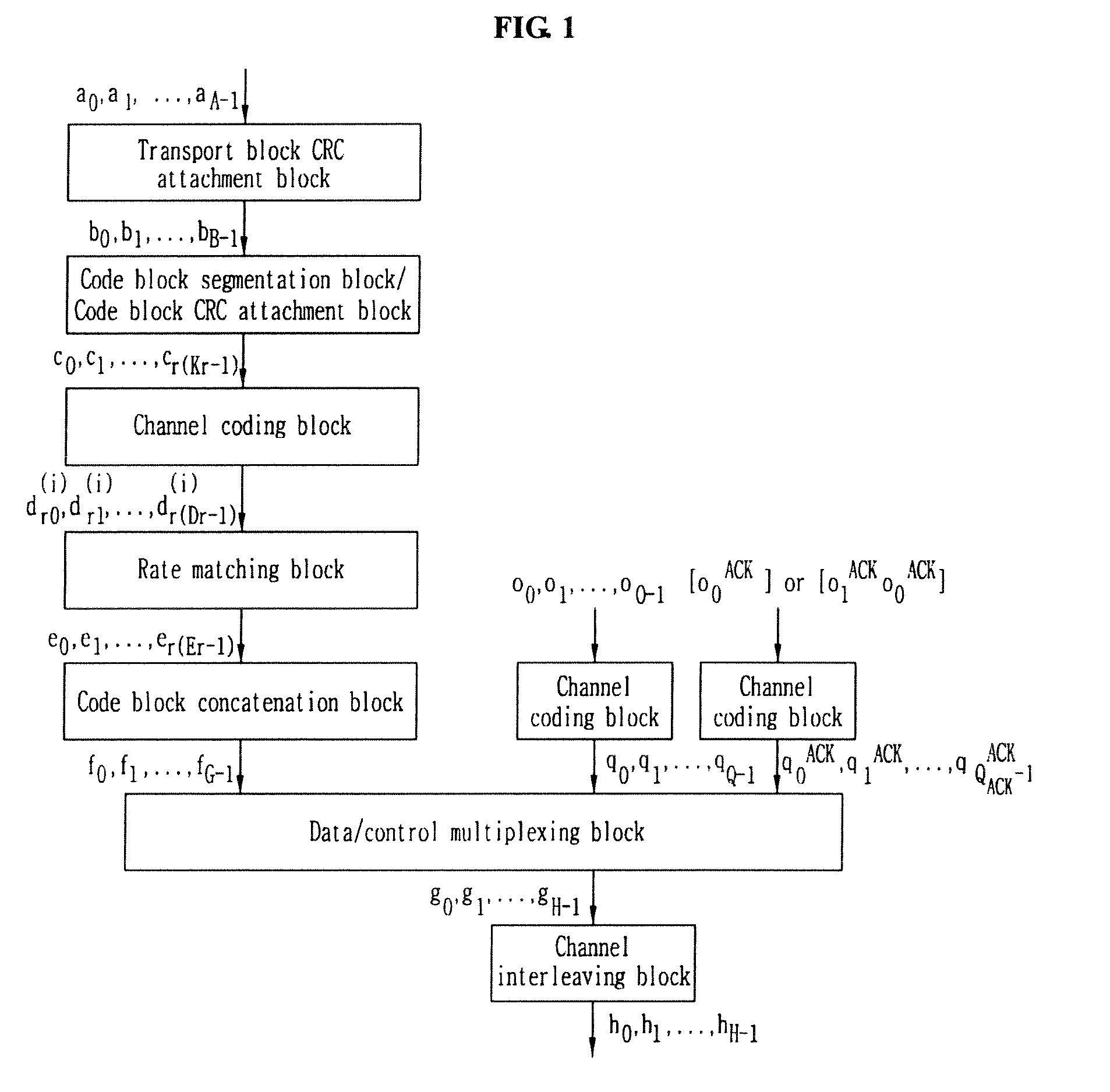
Method for multiplexing data and control information
a control information and data technology, applied in multiplex communication, fault response, signalling characterisation, etc., can solve the problems of increasing power consumption for decoding code blocks, affecting the ability and affecting the accuracy of control information, so as to improve the capability of wireless radio communication systems
- Summary
- Abstract
- Description
- Claims
- Application Information
AI Technical Summary
Benefits of technology
Problems solved by technology
Method used
Image

Examples
embodiment 1
[0079]FIG. 7 illustrates a method for multiplexing and mapping data information and control information to a set of resource elements according to an exemplary embodiment of the present invention.
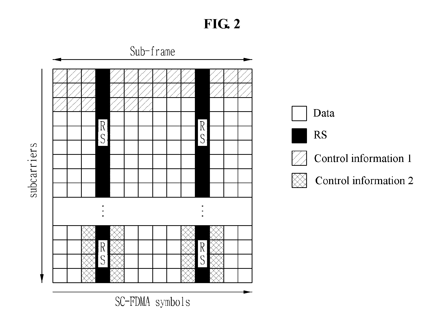
[0080]Referring to FIG. 7, control information 1 is mapped in a time axis (symbol axis) direction and control information 2 is mapped to resource elements corresponding to symbols next to symbols to which an RS is mapped. That is, the control information 2 is mapped to the above-described first symbol period area.
[0081]The control information 1 is mapped to one or more successive resource elements including the last resource element except for resource elements allocated for RS mapping within the whole area shown in FIG. 7. The control information 1 may be mapped in order of (1)→(2). Namely, the control information 1 may be mapped in a forward mapping order from the first resource element of an area to which the control information 1 is mapped. Alternatively, the control information 1 may b...
embodiment 2
[0085]FIG. 8 illustrates a method for multiplexing and mapping data information and control information to a set of resource elements according to another exemplary embodiment of the present invention.
[0086]In FIG. 8, control information 1 is mapped by the same method as the method used in FIG. 7. Control information 2 and control information 3 are mapped to a first symbol period area. The control information 2 is mapped in a forward, backward, or specific mapping order in the first symbol period area. The control information 3 is mapped in a forward, backward, or specific mapping order in an area except for an area to which the control information 2 is mapped in the first symbol period area. If the control information 3 does not exist, the method of FIG. 8 is the same as the method of FIG. 7.
[0087]In FIG. 8, the control information 1 does not puncture data information. Namely, the control information 1 rate-matches with the data information. The control information 1 may be constru...
embodiment 3
[0090]FIG. 9 illustrates a method for multiplexing and mapping data information and control information to a set of resource elements according to a further exemplary embodiment of the present invention.
[0091]In FIG. 9, control information 1 is mapped by the same method as the method used in FIG. 7. Control information 2 and control information 3 are mapped to resource elements of the first symbol period area. The control information 2 is mapped in a forward, backward, or specific mapping order in the first symbol period area. The control information 3 may be mapped in a forward, backward, or specific mapping order to the first symbol period area, except for an area to which the control information 1 is mapped within the first symbol period area. If the control information 2 does not exist, the control information 1 and the control information 3 are mapped with dropping the control information 2 in FIG. 9, and if the control information 3 does not exist, the control information 1 an...
PUM
 Abstract
Description
Claims
Application Information