

Pain-alleviating orthopaedic appliance
a technology for orthopaedic appliances and pain relief, applied in non-surgical orthopedic devices, medical science, bandages, etc., can solve the problems of increased neural tension and difficulty in hiding under everyday clothing, and achieve the effect of reducing the size of the appliance and minimizing the size and quantity of material
- Summary
- Abstract
- Description
- Claims
- Application Information
AI Technical Summary
Benefits of technology
Problems solved by technology
Method used
Image

Examples
Embodiment Construction
[0035]Reference will now be made in detail to the present preferred embodiments of the invention, an example of which is illustrated in the accompanying drawings. The method and corresponding steps of the invention will be described in conjunction with the detailed description of the system.
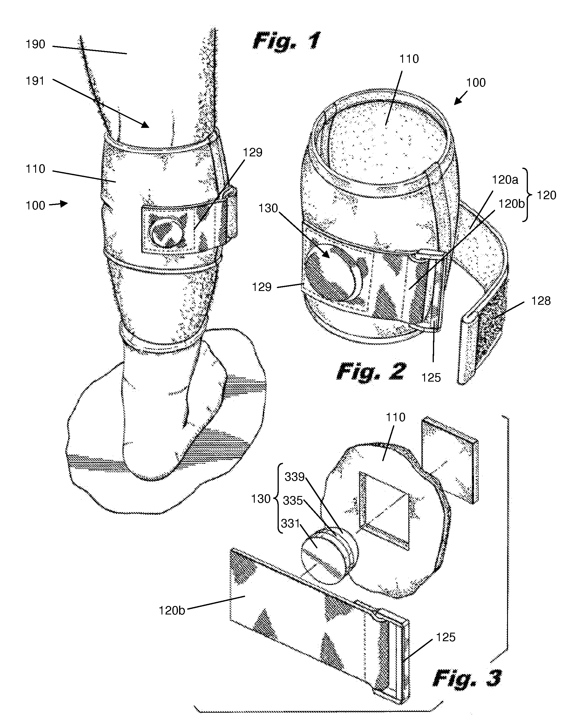
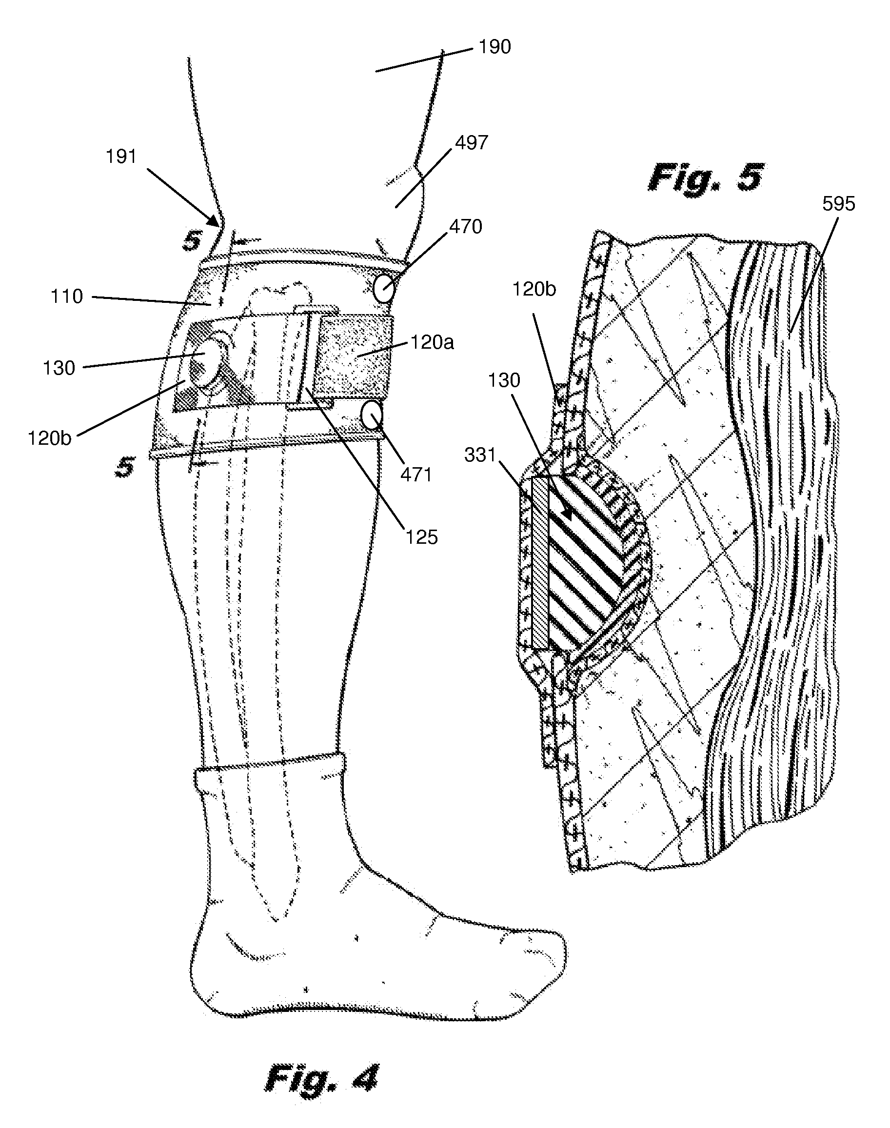
[0036]The devices and methods presented herein may be used for treatment of pain associated with spasming of the soleus muscle of the calf. Such pain can be experienced by the patient in a number of places, including in the buttocks or lower back.
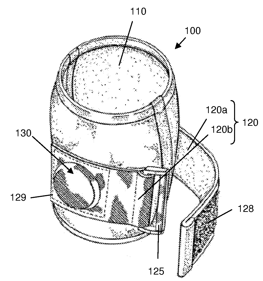
[0037]In accordance with the invention, the invention includes, in one aspect, an orthopaedic appliance for reducing pathological tension on a patient's peroneal nerve. The orthopaedic appliance includes a body configured for placement below the popliteal crease of a patient's leg, a protrusion extending inwardly from the body, positioned on the body to apply pressure on a proximal portion of the soleus muscle, and an adjustable strap portion extending a...
PUM
 Abstract
Description
Claims
Application Information