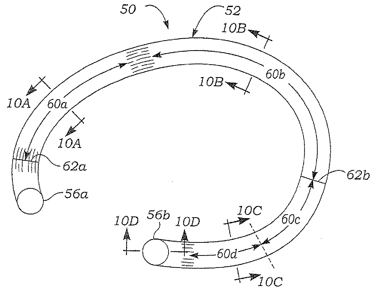
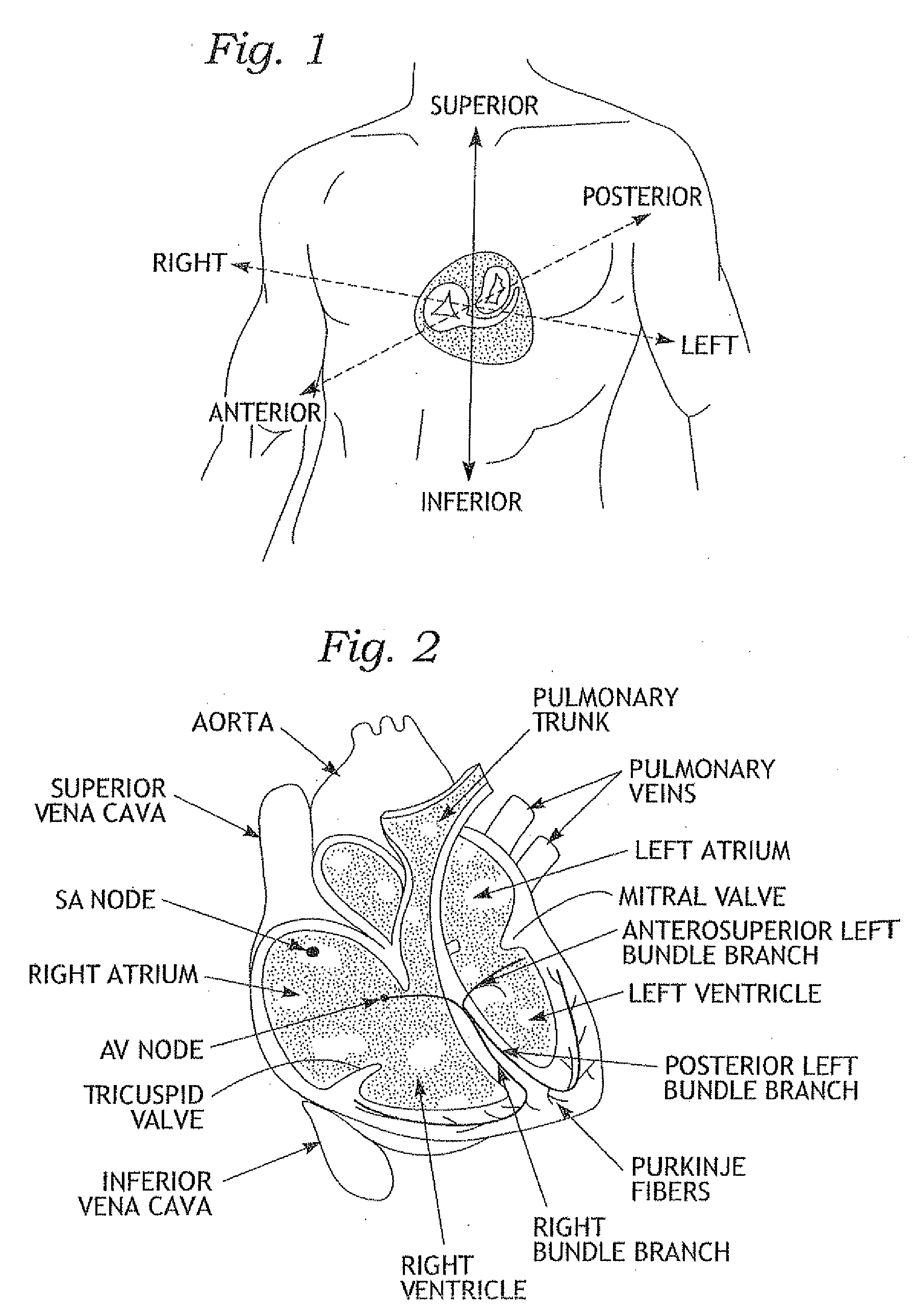
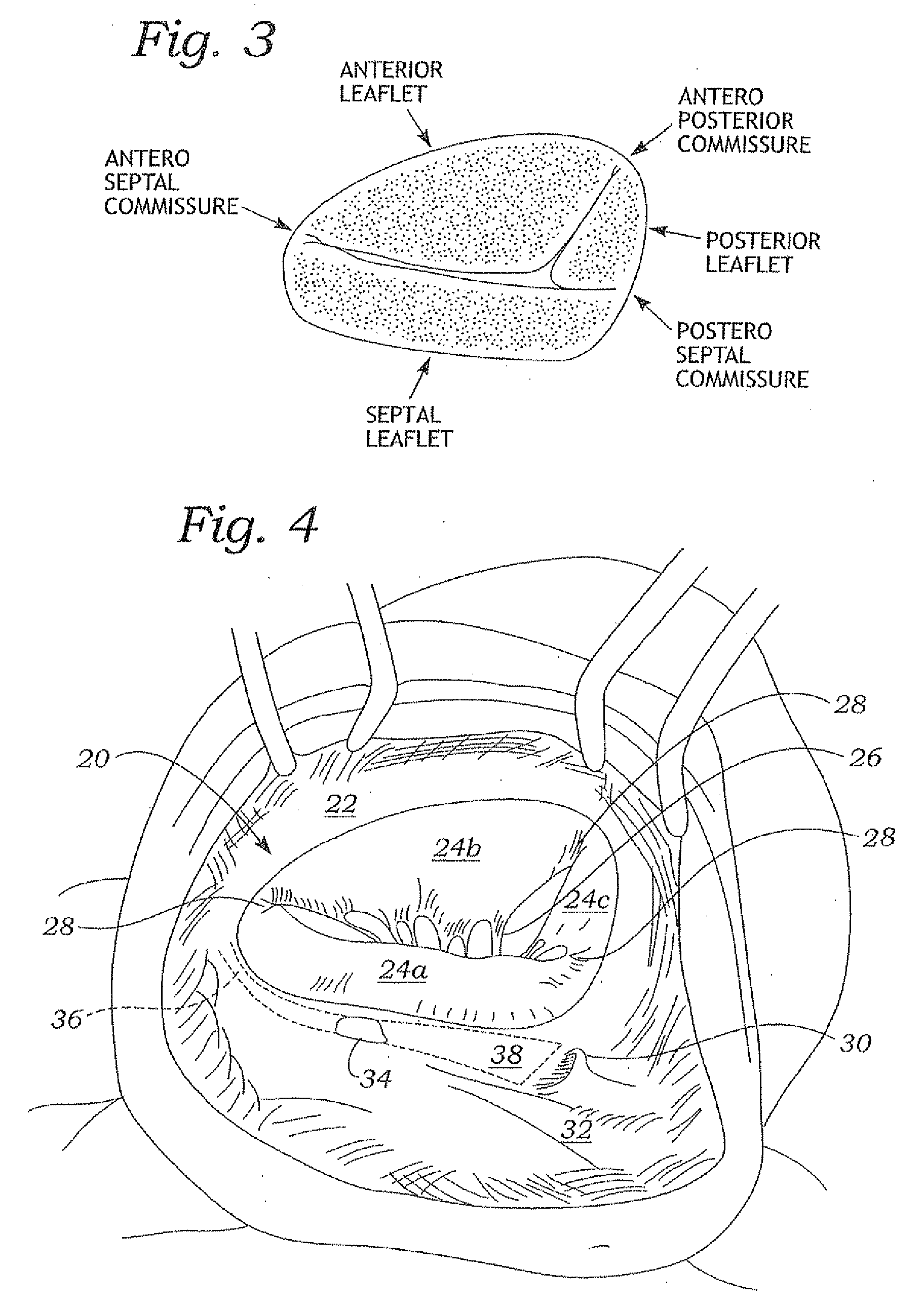
[0038]The present invention provides an improved tricuspid annuloplasty ring that better conforms to the native annulus and is shaped to protect certain features of the surrounding anatomy. The ring of the present invention is designed to support a majority of the tricuspid annulus without risking injury to the leaflet tissue and heart's conductive system, such as the AV node 34 and bundle of His 36 (see FIG. 4). Additionally, the present ring is contoured to better approximate the three-dimensional shape of the tricuspid annulus; specifically, the ring is substantially planar but includes a bulge in the inflow direction at the location of the bulge created by the adjacent aorta. The bulge helps reduce stress between the ring and surrounding tissue, and thus the potential for tearing or ring dehiscence.
[0039]Another feature that matches the present tricuspid ring with the physiological features of the annulus is a variable flexibility from a relatively stiff first segment to a relatively flexible fourth segment. This varying flexibility permits the ring to adapt (harmonize) its motion and 3-dimensional shape to that of the annulus, rather than impose its own motion and 3-D geometry thereto which tends to increase the risk of ring dehiscence. In particular, the motion of the tricuspid annulus during systole-diastole is believed to exert some torsional forces on the implanted ring, and the variable flexibility accommodates such torques. Moreover, localized points of flexibility or “hinges” around the ring as described herein may best conform and harmonize the physical properties of the ring to the annulus motion, while at the same time providing the needed corrective support.
[0040]It should also be understood that certain features of the present tricuspid ring might also be applicable and beneficial to rings for other of the heart's annuluses. For instance, the present ring includes upturned or bent free ends that help reduce abrasion on the adjacent leaflets. The same structure might be used in a discontinuous ring for the mitral valve annulus.
[0041]The term “axis” in reference to the illustrated ring, and other non-circular or non-planar rings, refers to a line generally perpendicular to the ring that passes through the area centroid of the ring when viewed in plan view. “Axial” or the direction of the “axis” can also be viewed as being parallel to the direction of blood flow within the valve orifice and thus within the ring when implanted therein. Stated another way, the implanted tricuspid ring orients about a central flow axis aligned along an average direction of blood flow through the tricuspid annulus. Although the rings of the present invention are 3-dimensional, portions thereof are planar and lie perpendicular to the flow axis.
[0042]FIGS. 7A-7C illustrate, in plan and septal and anterior elevational views, a tricuspid ring 50 of the present invention having a ring body 52 generally arranged about an axis 54 and being discontinuous so as to define two free ends 56a, 56b. The axis 54 in FIG. 7A lies at the centroid of the ring or along of the axis of blood flow through the ring 50 when implanted, and it will be understood that the relative directions up and down are as viewed in FIG. 7B. Using this convention, the ring 50 is designed to be implanted in a tricuspid annulus such that blood will flow in the downward direction.
[0043]As seen in FIGS. 7A-7C and also in FIGS. 9A-9C, the ring body 52 is substantially asymmetric and ovoid with the first free end 56a located adjacent the antero-septal commissure (see FIG. 3). The ring body 52 extends in a clockwise direction, as seen looking at the inflow side in FIG. 7A, around a first segment 60a corresponding to the aortic part of the anterior leaflet, a second segment 60b corresponding to the remaining part of the anterior leaflet and ending at the postero septal commissure, a third segment 60c from the postero septal commissure to a line 61 part way along the septal leaflet, and a fourth segment 60d that terminates in the second free end 56b at a septal point. The nomenclature for these segments is taken from the standard anatomical nomenclature around the tricuspid annulus as seen in FIG. 3.
[0044]The precise relative dimensions of the segments may vary, but they are generally as indicated in the view of FIG. 7A. That is, the second segment 60b is the largest, followed by the first segment 60a, and then the smaller third segment 60c and fourth segment 60d. It should be further noted that the term “asymmetric” means that there are no planes of symmetry through the ring body 52 looking from the inflow side, and “ovoid” means generally shaped like an egg with a long axis and a short axis, and one long end larger than the other.
[0045]FIG. 8 shows the tricuspid ring 50 in plan view after having been implanted or otherwise affixed to a tricuspid valve. To quantify relative to the native anatomy, the combined first and second segments 60a and 60b extend approximately around the tricuspid annulus between the two commissures 28 that bookend the septal leaflet 24a. Accordingly, a pair of commissure markers 62a, 62b on the exterior of the ring body 52 facilitate implantation by registering the ring 50 with respect to the commissures 28. The markers 62a, 62b are typically radially-oriented colored thread fastened to a fabric covering on the ring.
[0046]A majority of the ring body 52 is planar except for the free ends 56a, 56b which are upturned and the first segment 60a and a part of fourth segment 60d that are bowed upward. (To repeat, the “up” direction is merely for purpose of clarity herein and is synonymous with the inflow direction). As with existing rings, sizes 26 mm through 36 mm in 2 mm increments are available having outside diameters (OD) between 31.2-41.2 mm, and inside diameters (ID) between 24.3-34.3 mm. Again, these diameters are taken along the “diametric” line spanning the greatest length across the ring, as seen in FIG. 5A. It should be mentioned that the present invention is not limited to the aforementioned range of sizes, and larger rings of 38 or 40 mm OD are also possible, for example.
[0047]A gap G′ between the two free ends 56a, 56b is substantially larger than in certain rings of the prior art to reduce the risk of suturing into the AV node or bundle of His, and to accommodate variations in anatomy and location of the bundle of His. In particular, the gap G′ is preferably between about 40%-50% of the labeled size, preferably between about 43-45%. In one configuration, the gap G′ is about 40% of the size of the long axis of the ring, which is typically the labeled size in millimeters. In absolute terms, the gap G′ is desirably between about 10-18 mm, depending on the labeled size. For instance, the gap G′ is preferably about 13.6 mm for a size 34 ring (about 40% of the labeled size). On the other hand, the gap G′ is not too large to reduce the effective support for the septal leaflet 24a. Preferably, the fourth segment 60d of the ring 50 of the present invention extends at least half of the way around the septal leaflet 24a.
[0048]In a preferred embodiment, the gap G′ is larger than the gap G in the rigid C-shaped Carpentier-Edwards Classic® Tricuspid Annuloplasty Ring, seen in FIGS. 5A and 5B. The gap G for the various sizes of Classic® Rings ranges between about 5-8 mm, or between about 19%-22% of the labeled size. At the same time, the gap G′ of the ring of the present invention is larger than the gap in the flexible C-shaped Sovering™ tricuspid ring from Sorin Biomedica Cardio S.p.A. The gap for the various sizes of the Sovering™ ranges between about 18-24 mm, or between about 60%-70% of the labeled size. Therefore, the gap G′ of the ring of the present invention is preferably greater than 8 mm and less than 18 mm, or is between about 23%-59% of the labeled size (typically equal to the dimension in millimeters of the long axis of the ring).
[0049]The free ends 56a, 56b of the exemplary ring 50 are upturned in the inflow direction so as to help reduce abrasion on the adjacent leaflets (septal, or both septal and antero-superior). Prior rings that are not completely flexible terminate in ends that are extensions of the ring periphery, that is, they do not deviate from the paths that the adjacent segments of the ring follow. As will be explained below, the present ring 50 desirably includes a core member that provides at least some rigidity and structural support for the annulus. The upturned ends 56a, 56b present curved surfaces that the constantly moving leaflets might repeatedly contact, as opposed to point surfaces so that forcible abrasion of the moving leaflets in contact with the ends of the ring is avoided.
[0050]As seen in FIGS. 7B and 7C, the exemplary ring 50 also includes an upward arcuate bow or bulge 64 in the first segment 60a, and another upward bulge 65 in the fourth segment 60d. The “aortic” bulge 64 accommodates a similar contour of the tricuspid annulus due to the external presence of the aorta and desirably extends from near the first free end 56a along first segment 60a to a location that corresponds to the end of the aortic part of the anterior leaflet. Prior tricuspid rings are substantially planar, and if at all rigid they necessarily deform the annulus to some extent at this location. The aortic bulge 64 helps reduce stress upon implant and concurrently reduces the chance of dehiscence, or the attaching sutures pulling out of the annulus. The axial height hb of the aortic bulge 64 above the nominal top surface of the ring body 52, as indicated in FIG. 9C, is between about 3-9 mm, preferably about 6 mm. The “septal” bulge 65 conforms to the slight bulging of the septal leaflet attachment in this area. The axial height hs of the septal bulge 65 above the nominal top surface of the ring body 52, as indicated in FIG. 9B, is between about 2 to 4 mm. These two bulges 64, 65 provide a “saddle shape” to the ring body 52.
[0051]Now with particular reference to FIGS. 9A-9C and 10A-10D, the tricuspid ring 50 of the present invention is seen partially cutaway and in sections to illustrate further exemplary features. As seen best in the cutaway portion of FIG. 9B, the ring body 52 preferably comprises an inner core 70 encompassed by an elastomeric interface 72 and an outer fabric covering 74.
[0052]The inner core 70 extends substantially around the entire periphery of the ring body 52 and is a relatively rigid material such as stainless steel, titanium, Elgiloy (an alloy primarily including Ni, Co, and Cr), Nitinol, and even certain polymers. The term “relatively rigid” refers to the ability of the core 70 to support the annulus without substantial deformation, and implies a minimum elastic strength that enables the ring to maintain its original shape after implant even though it may flex somewhat. Indeed, as will be apparent, the ring desirably possesses some flexibility around its periphery. To further elaborate, the core 70 would not be made of silicone, which easily deforms to the shape of the annulus and therefore will not necessarily maintain its original shape upon implant.
[0053]The elastomeric interface 72 may be silicone rubber molded around the core 70, or a similar expedient. The elastomeric interface 72 provides bulk to the ring for ease of handling and implant, and permits passage of sutures though not significantly adding to the anchoring function of the outer fabric covering 74. The fabric covering 74 may be any biocompatible material such as Dacron® (polyethylene terepthalate). As seen in FIGS. 10A-10C, the elastomeric interface 72 and fabric covering 74 project outwards along the outside of the ring 50 to provide a platform through which to pass sutures.
[0054]As mentioned above, the ring 50 of the present invention may possess a varying flexibility around its periphery. In general, the ring 50 is desirably stiffer adjacent the first free end 56a than adjacent the second free end 56b, and preferably has a gradually changing degree of flexibility for at least a portion in between. For instance, the first segment 60a may be relatively stiff while the remainder of the ring body 52 gradually becomes more flexible through the second segment 60b, third segment 60c, and fourth segment 60d. In a preferred embodiment, the fourth segment 60d is more flexible than the third segment 60c.
[0055]With reference to FIG. 7A, the reader will appreciate that the flexibility of the fourth segment 60d accommodates the inward movement of the annulus in that sector from fluid dynamic closing forces on the valve, and therefore reduces the chance of dehiscence. More particularly, radial forces exerted on the ring in the vertical direction, or along the small axis, will act on the flexible fourth segment 60d and proportionately bend it inward, as indicated in phantom. This reduction in the antero-septal ring dimension, in turn, will reduce tension on the native valve leaflets that pull inward from valve closing forces. Tests have been conducted to determine the amount of force and movement associated with the septal aspect of the tricuspid annulus in both systole and diastole. Consequently, a preferred flexibility for the fourth segment 60d has been determined and quantified in terms of the amount of desirable deformation under a given load. In one embodiment, the flexibility of the fourth segment 60d is such that it deforms inward by about 10% of the antero-septal (small axis) ring dimension under maximum load, typically resulting from right ventricular pressures of up to 70 mm Hg. In contrast, left ventricular pressures of up to 120 mm Hg are handled by a more robust mitral annulus. The tricuspid annulus is more fragile and implanted annuluplasty rings are somewhat more prone to dehiscence.
[0056]Another potential configuration of variable flexibility consists of one or more points of localized flexibility, or “hinge points,” that may supplement the aforementioned gradually changing stiffness or be incorporated into an otherwise constant stiffness ring. The locations of the contemplated hinges are best described with reference to FIGS. 7A and 7B.
[0057]A central hinge created by an area of the ring body 52 that is locally more flexible than adjacent sectors is desirably located mid-way along the second segment 60b, as indicated by a hinge line 66. This hinge is located approximately at the center of the length of the ring body 52, and permits the segments on either side to flex or twist with respect to one another. Alternatively, two generally diametrically-opposed hinge points indicated by hinge lines 61 and 67 may be provided. These hinges are located at the upward bulges 64, 65 in the ring body 52, and provide “saddle” flexibility so that the ring flexes generally in a plane intersecting the bulges. A ring according to the present invention may have one or more of these hinges. Also, as mentioned above, the discrete hinges or points of flexibility may be incorporated into rings having constant or variable flexibility, as described above. Finally, though 3-dimensional rings are shown, the several embodiments of flexibility described herein may also be provided in a flat, planar tricuspid ring, and with or without the increase gap between the free ends.
[0058]In one exemplary construction, the ring body includes a core 70 made of a plurality of concentric peripheral bands having an axial dimension which is larger adjacent the first free end 56a than adjacent the second free end 56b. Sectional FIGS. 10A-10C illustrate this embodiment. The core 70 in the first segment 60a (and possibly in a portion of the second segment 60b) is as seen in FIG. 10A, with six (6) concentric bands of a material such as Elgiloy. In the section of FIG. 10B, which is taken through the second segment 60b, a section of the core 701 still comprises six concentric bands, but its axial height is reduced relative to the height of the core as seen in FIG. 10A. Finally, FIG. 10C shows a section through the third segment 60c wherein a further section of the core 70″ is further reduced in height but also only comprises four (4) concentric bands, with two of the bands having terminated or tapered off somewhere between sections 10B and 10C. Of course, this construction is entirely exemplary and the core 70 could also be made of a single integral member that gradually tapers down in size, among other alternatives. Several other alternatives are disclosed in U.S. Pat. No. 5,104,407 to Lam, et al., the disclosure of which is expressly incorporated herein by reference.
[0059]FIG. 10D shows the internal structure of the ring body 52 at the second end 56b. The core 70 is shown bending upward into close proximity with the extreme tip of the free end 56b, though it is protected by the elastomeric interface 72 and the outer fabric covering 74. Desirably, the core 70 has its greatest flexibility at this location, which is mid-way around the septal leaflet side of the tricuspid annulus. The upward bend of the core 70 and ring body 52 desirably makes an angle θ of between 45°-90°, preferably greater than 60°. Furthermore, the axial height he, as indicated in FIG. 9C, of the free ends 56a, 56b above the nominal top surface of the ring body 52 is between about 1-4 mm, preferably about 2 mm, and preferably the two free ends project upward the same distance (although such a configuration is not an absolute requirement). Because of the flexibility of the ring body 52 at the second end 56b, there is a reduction in the antero-septal dimension of the ring depending on the load applied by the annulus in the small axis (vertical) dimension.
[0060]While the foregoing is a complete description of the preferred embodiments of the invention, various alternatives, modifications, and equivalents may be used. Moreover, it will be obvious that certain other modifications may be practiced within the scope of the appended claims.