[0016]The
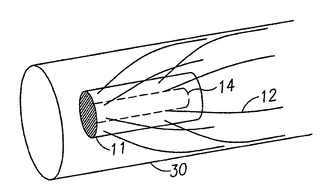
robot is generally comprised of a central
torso or body, and flexible fibers attached as cantilevers at an angle to the central
torso. The fibers should be unloaded if not in contact with any surrounding surface. The fibers should be sufficiently long that, when the device is applied to the inner surface walls of the tube it is intended to negotiate, or to the surface it is intended to crawl along, a portion of the
fiber at the end remote from the
torso becomes parallel to the surface, making contact with the surface along at least a part of its length. The fibers may have varying flexibility, increasing from base to tip, to enable flexion in such a way as to assist this effect.
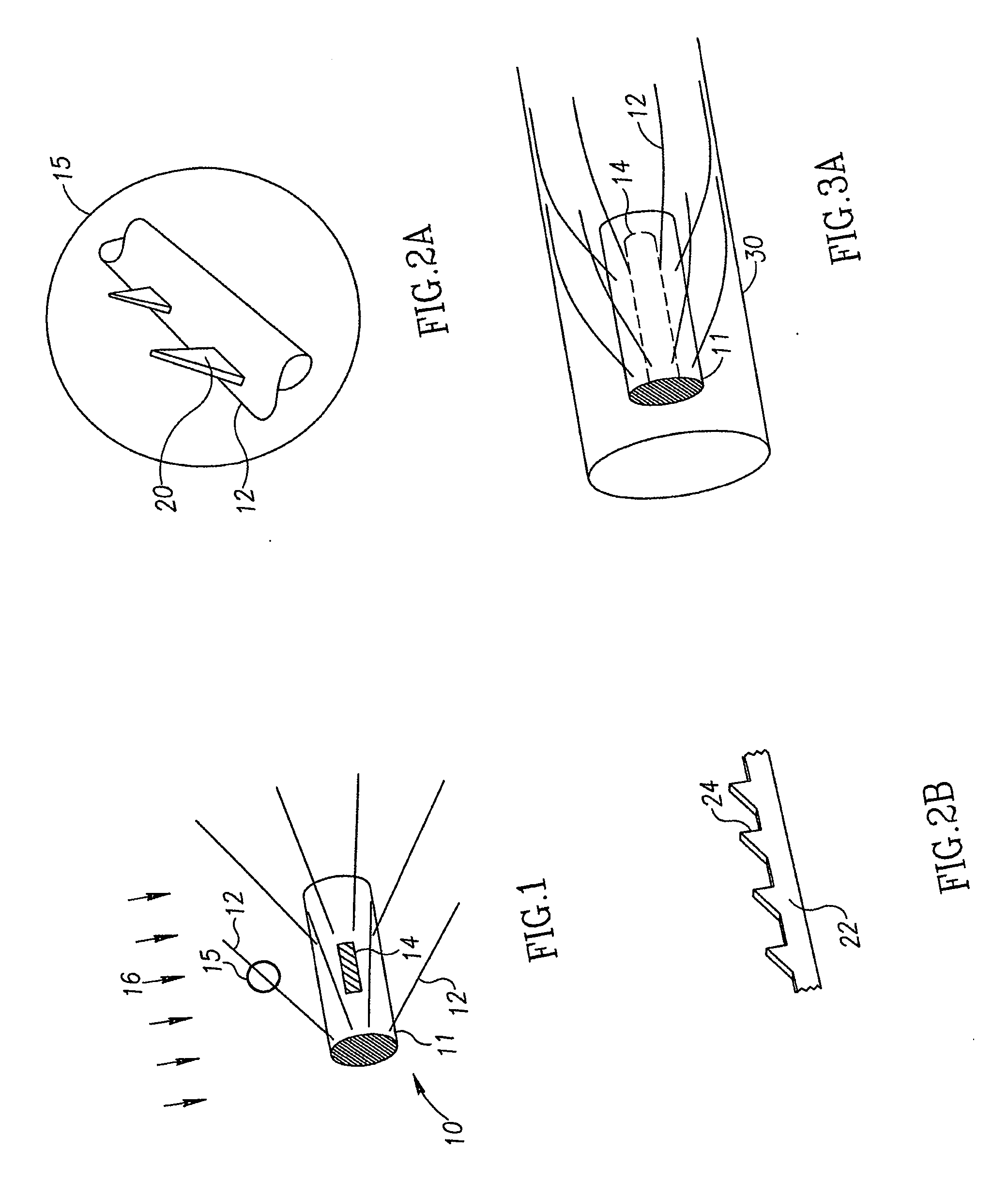
[0017]The surface of the fibers should have an anisotropic
coefficient of friction along at least a portion of their length remote from the torso, such that they grip the opposing surface more strongly in one direction of
relative motion than in the other direction. This may be achieved by providing the fibers with spikes extended from their surface, providing contact with surrounding surfaces through the spikes. The fibers are long enough to maintain contact with the surrounding surfaces during motion. The
fiber's extended spikes may be slanted at an angle to the fiber, further referred to as the spike angle. The angle between the spikes and the co-operating friction surface, further referred to as
contact angle, determines the
friction force with the surrounding surface. As a result of the fiber's flexion, the
contact angle is approximately equal to the spike angle, allowing the maintenance of an optimal and constant
friction force throughout the motion.
[0018]The fibers' spikes provide anchoring points to the surrounding surface in the direction opposite to the slant of the spikes, thus stopping backward motion, while enabling slipping movement in their slanted direction, resulting in an anisotropic
friction coefficient. The locomotion is optimal when the difference between friction forces acting during movement in opposite directions is maximal. This difference depends both on the difference between the friction coefficients acting in opposite directions, and on the distributed normal forces acting on the contact area with the surrounding surfaces. These two factors depend upon the extent of the contact area of the fibers with their surrounding surfaces and upon the
contact angle. Thus a proposed structure having a variable fiber cross section enables optimization of both parameters, maintaining a constant contact angle, a large
normal force, and a long parallel contact portion of fiber with the surrounding walls. A particularly simple method of achieving a higher
normal force due to a variable flexibility fiber is by use of fibers having a thicker base end than that of the tip end. The base end then provides increased stiffness, and hence increased
normal force at the contact end, while the contact end has the desired increased flexibility to make contact with a longer section of the opposing surface.
[0019]Since that portion of the fibers making contact with the surrounding surface is parallel to the surrounding surface, the contact angle remains constant throughout the motion. The length of the fibers may be such that they significantly exceed the distance between the device body and the surrounding surface. If the fibers were stiff, as in prior art vibrating
bristle devices which rely on
bristle tip friction, this would be impractical since the fibers in such devices have only one contact point at the tip of the fiber, and lengthening the fibers would result in a smaller angle of contact at the tip, and reduced
friction coefficient. Hence if applied as an in-
pipe apparatus, the flexibility of the fibers in the exemplary devices described in the present application, enables application of a single one of such devices to a wide range of diameters. This property makes the invention desirable, for example, for use in medical applications where arteries, the
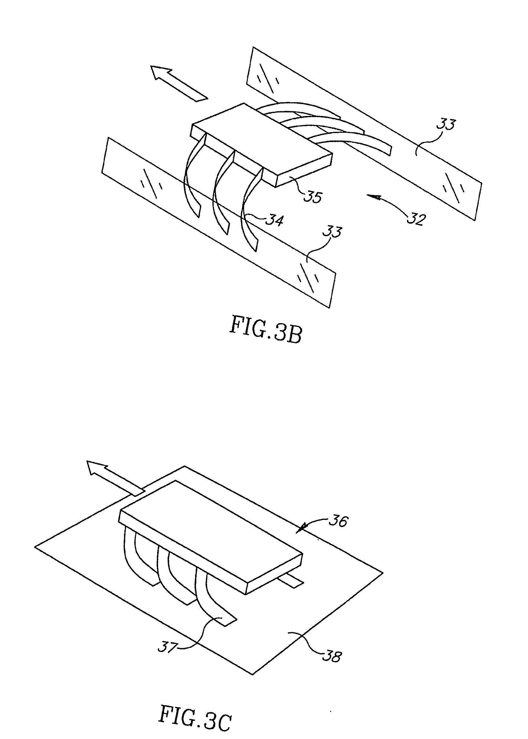
gastrointestinal tract, and other internal lumens may vary greatly in diameter along their length. The considerations above also apply for two bounding walls for confined planar motion, and for rotational movements which are attractive for use in Micro Electro
Mechanical System (MEMS) applications, but had been limited till now due to design and manufacturing limitations.
[0020]Locomotion is achieved due to random vibrations in any direction or plane applied to the torso of the device. A
robot constructed according to these aspects of the present invention progresses due to flexion of its fibers. Thus, any vibration causing the fibers to flex will result in progression. One possible actuation embodiment for such devices is to use an onboard
magnet or ferromagnetic
slug while inducing a time varying
magnetic field upon it. This example enables unlimited
operation time, since the
activation energy for generating the vibration is provided externally and is not dependent on the use of onboard batteries, while also maintaining simplicity of operation. It is possible to use magnetic induced actuation since the vibration does not need to be controlled in any manner. Any
random vibration will enable the device to function correctly. As an alternative to causing the body to vibrate, it is possible to generate the vibrations directly in the fibers, such as by making them of a magnetized or a magnetic material and applying an external alternating
magnetic field, or by any other suitable method.

