Vibrating robotic crawler

a robotic crawler and crawler technology, applied in the field of robotic devices, can solve the problems of limiting miniaturization, complicating operation, and most methods commonly used cannot operate in confined spaces, and achieve the effects of increasing rigidity, increasing normal force, and optimizing and constant friction for

Active Publication Date: 2012-10-23
TECHNION RES & DEV FOUND LTD
View PDF22 Cites 6 Cited by
  • Summary
  • Abstract
  • Description
  • Claims
  • Application Information

AI Technical Summary

Benefits of technology

[0017]The robot is generally comprised of a central torso or body, and flexible fibers attached as cantilevers at an angle to the central torso. The fibers should be unloaded if not in contact with any surrounding surface. The fibers should be sufficiently long that, when the device is applied to the inner surface walls of the tube it is intended to negotiate, or to the surface it is intended to crawl along, a portion of the fiber at the end remote from the torso becomes parallel to the surface, making contact with the surface along at least a part of its length. The fibers may have varying flexibility, increasing from base to tip, to enable flexion in such a way as to assist this effect.
[0018]The surface of the fibers should have an anisotropic coefficient of friction along at least a portion of their length remote from the torso, such that they grip the opposing surface more strongly in one direction of relative motion than in the other direction. This may be achieved by providing the fibers with spikes extended from their surface, providing contact with surrounding surfaces through the spikes. The fibers are long enough to maintain contact with the surrounding surfaces during motion. The fiber's extended spikes may be slanted at an angle to the fiber, further referred to as the spike angle. The angle between the spikes and the co-operating friction surface, further referred to as contact angle, determines the friction force with the surrounding surface. As a result of the fiber's flexion, the contact angle is approximately equal to the spike angle, allowing the maintenance of an optimal and constant friction force throughout the motion.
[0019]The fibers' spikes provide anchoring points to the surrounding surface in the direction opposite to the slant of the spikes, thus stopping backward motion, while enabling slipping movement in their slanted direction, resulting in an anisotropic friction coefficient. The locomotion is optimal when the difference between friction forces acting during movement in opposite directions is maximal. This difference depends both on the difference between the friction coefficients acting in opposite directions, and on the distributed normal forces acting on the contact area with the surrounding surfaces. These two factors depend upon the extent of the contact area of the fibers with their surrounding surfaces and upon the contact angle. Thus a proposed structure having a variable fiber cross section enables optimization of both parameters, maintaining a constant contact angle, a large normal force, and a long parallel contact portion of fiber with the surrounding walls. A particularly simple method of achieving a higher normal force due to a variable flexibility fiber is by use of fibers having a thicker base end than that of the tip end. The base end then provides increased stiffness, and hence increased normal force at the contact end, while the contact end has the desired increased flexibility to make contact with a longer section of the opposing surface.
[0020]Since that portion of the fibers making contact with the surrounding surface is parallel to the surrounding surface, the contact angle remains constant throughout the motion. The length of the fibers may be such that they significantly exceed the distance between the device body and the surrounding surface. If the fibers were stiff, as in prior art vibrating bristle devices which rely on bristle tip friction, this would be impractical since the fibers in such devices have only one contact point at the tip of the fiber, and lengthening the fibers would result in a smaller angle of contact at the tip, and reduced friction coefficient. Hence if applied as an in-pipe apparatus, the flexibility of the fibers in the exemplary devices described in the present application, enables application of a single one of such devices to a wide range of diameters. This property makes the invention desirable, for example, for use in medical applications where arteries, the gastrointestinal tract, and other internal lumens may vary greatly in diameter along their length. The considerations above also apply for two bounding walls for confined planar motion, and for rotational movements which are attractive for use in Micro Electro Mechanical System (MEMS) applications, but had been limited till now due to design and manufacturing limitations.
[0021]Locomotion is achieved due to random vibrations in any direction or plane applied to the torso of the device. A robot constructed according to these aspects of the present invention progresses due to flexion of its fibers. Thus, any vibration causing the fibers to flex will result in progression. One possible actuation embodiment for such devices is to use an onboard magnet or ferromagnetic slug while inducing a time varying magnetic field upon it. This example enables unlimited operation time, since the activation energy for generating the vibration is provided externally and is not dependent on the use of onboard batteries, while also maintaining simplicity of operation. It is possible to use magnetic induced actuation since the vibration does not need to be controlled in any manner. Any random vibration will enable the device to function correctly. As an alternative to causing the body to vibrate, it is possible to generate the vibrations directly in the fibers, such as by making them of a magnetized or a magnetic material and applying an external alternating magnetic field, or by any other suitable method.

Problems solved by technology

Current techniques for providing autonomous motion down a lumen generally involve a relatively complicated mechanism with multiple moving parts, which restricts miniaturization because of current technological limitations.
Moreover those techniques often require sequential controlled actuations, thus complicating their operation.
Furthermore most methods commonly used cannot operate in confined spaces such as relatively small pipes, or in environments other than those predetermined for the device.
Due to the complexity, the multiplicity of moving parts, the possible need of actuators, and control circuits, sensors and internal power sources, prior art mechanisms suffer size limitations, have complex assemblies and relatively high cost, specifically in narrow environments like pipes where miniaturization is essential.
More specifically for medical applications, where there is demand for biocompatible miniature systems with a minimal number of moving parts (for medical safety reasons) prior art mechanisms are generally far from optimal.
However the fiber's stiffness and the friction which is induced solely at the tips of the fibers limit the pipe diameter range to which such an apparatus may be applied.
In addition this apparatus is limited to uses within a pipe.
Bristle tip-based oscillational crawlers may be limited to specific spatial situations such as pipes having a predetermined diameter and with only small variations in diameter, and moreover to specifically sequential or controlled oscillations.

Method used


Image

  • Vibrating robotic crawler
  • Vibrating robotic crawler
  • Vibrating robotic crawler

Examples


Embodiment Construction

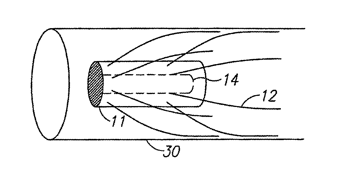
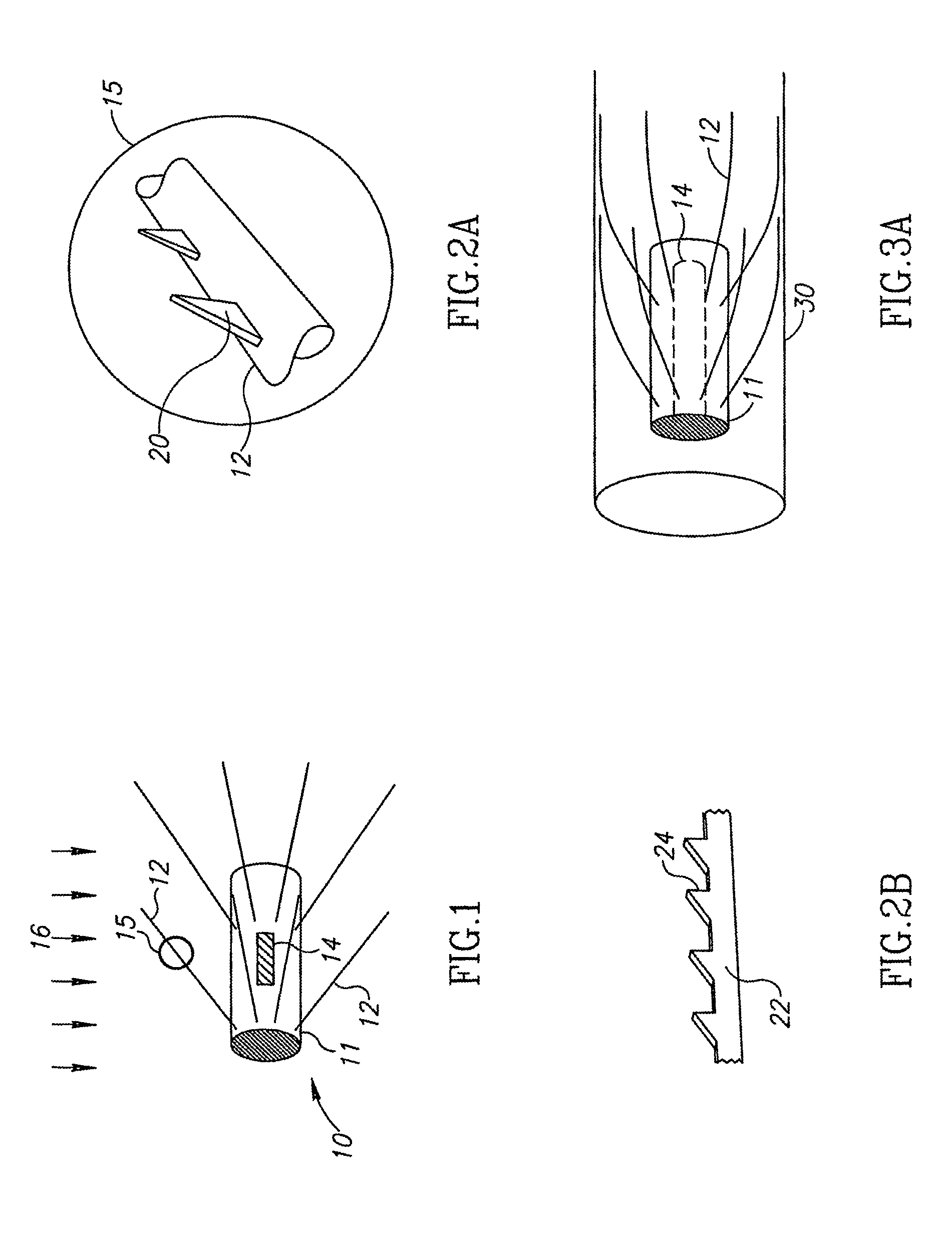
[0054]Reference is now made to FIG. 1 which illustrates schematically an example of a linear motion vibrating robotic crawler 10 according to one aspect of the present invention. To the body 11 of the device may be attached a number of flexible fibers 12 having superficial anisotropic friction with the opposing surface relative to which the robotic crawler is intended to move. The fibers are attached to the body such that they are generally oriented at angles having the same sense to the axis of the body 11. In FIG. 1, the fibers are all shown oriented to the right of the drawing, meaning that they make an acute angle with the axis in the direction towards the right of the drawing. Although the fibers are all shown inclined at the same attachment angle in FIG. 1, this is not an essential condition for the operation of the device, and it will function so long as a majority of the fibers are generally inclined in one direction relative to a plane perpendicular to the axis of the body....


PUM


Abstract

An autonomous vibration-driven device, for motion through a lumen or along a surface, utilizing an array of flexible fibers attached to the body of the device. The outer surface of the fibers have an anisotropic coefficient of friction with the surface along which the device is to move, and the fibers extend from the device body such that at least some of the fibers are in contact with the walls along a part of their length. A transducer is used to vibrate the device, such that it moves down the lumen. The transducer can be either device borne or external. A rotary device is also described, utilizing an array of fibers disposed on the rotor's body, the fibers having an anisotropic coefficient of friction with a central stator or with an outer circular wall. A planar motion device is also described for crawling over a planar surface.

Description

[0001]This is a 35 U.S.C. §371 application of PCT / IL2008 / 000505, filed Apr. 13, 2008, and claims the benefit under 35 U.S.C. §120 of said PCT application, and further claims the benefit under 35 U.S.C. §119(e) of U.S. Provisional Patent Application U.S. Ser. No. 60 / 907,691, filed Apr. 13, 2007. The contents of these priority applications are incorporated herein by reference.FIELD OF THE INVENTION[0002]The present invention relates to a robotic device for crawling over a surface, whether plane or in a lumen, especially using vibration of the device to propel it by means of flexible fibers having an external surface with anisotropic friction with the surface on which the device is crawling.BACKGROUND OF THE INVENTION[0003]Current techniques for providing autonomous motion down a lumen generally involve a relatively complicated mechanism with multiple moving parts, which restricts miniaturization because of current technological limitations. Moreover those techniques often require sequ...

Claims


Application Information

Patent Timeline
Patent Type & Authority Patents(United States)
IPC IPC(8): H01L41/08
CPCB08B9/049B25J5/00B25J7/00F16L55/32A61B5/6876A61B1/00156A61M25/0116A61B5/6861A61B2560/066A61B2560/063Y10T74/18016A61B5/0215A61B5/026A61B5/02
Inventor SALOMON, ODEDSHVALB, NIRSHOHAM, MOSHE
Owner TECHNION RES & DEV FOUND LTD
Why Eureka
Try Eureka