Recessed LED Lighting Fixture

a technology of led lighting fixtures and recessed lighting, which is applied in the direction of fixed installation, lighting and heating equipment, instruments, etc., can solve the problems of general limitations of the size of the area of recessed lighting fixtures, and achieve the effect of reducing the size of the fixtur

Active Publication Date: 2009-11-26
IDEAL IND LIGHTING LLC
View PDF34 Cites 36 Cited by
  • Summary
  • Abstract
  • Description
  • Claims
  • Application Information

AI Technical Summary

Benefits of technology

[0007]Another object of the invention is to provide an improved recessed lighting fixture that is readily adaptable for a variety of mounting positions and situations.
[0017]Some other embodiments with small-sized light openings may have as few as three emitters each with the lens off-axially distributing its emitter light in a direction radially across the light opening. Therefore, a fixture, which has the light opening with a very small greatest dimension, may provide a very wide light-beam angle allowing illumination of a comparatively large area. Since, LEDs themselves are of a very small size, the size of such fixtures may depend only on the dimensions of the LED lenses. A small overall size of the fixture providing a wide light-beam angle according to the current invention allows the inventive lighting fixture to be mounted into a great variety of small structures, even including such portable structures as flashlights.
[0018]The off-axial light distribution, which allows a great widening of an angle at which LED-emitted light exits the fixture, is achieved with LED lenses specifically designed for directing mostly all of light from a selected emitter off-axially. A configuration of the lens surfaces provides a total internal reflection (TIR) allowing a minimal loss of light.
[0022]The configuration of the surfaces of the lens defines a high efficiency of light output which achieves minimal losses of light. The inventive lens has about 80-95% efficiency in usage of emitter light. In certain preferred embodiments only about 13% of light from the emitter is lost (not directed for useful illumination).

Problems solved by technology

Recessed lighting fixtures in general have certain limitations with respect to the size of the area that can be illuminated by a given fixture.
This can become a problem when architectural design preferences tend toward fewer fixtures and smaller openings.

Method used


Image

  • Recessed LED Lighting Fixture
  • Recessed LED Lighting Fixture
  • Recessed LED Lighting Fixture

Examples


Embodiment Construction

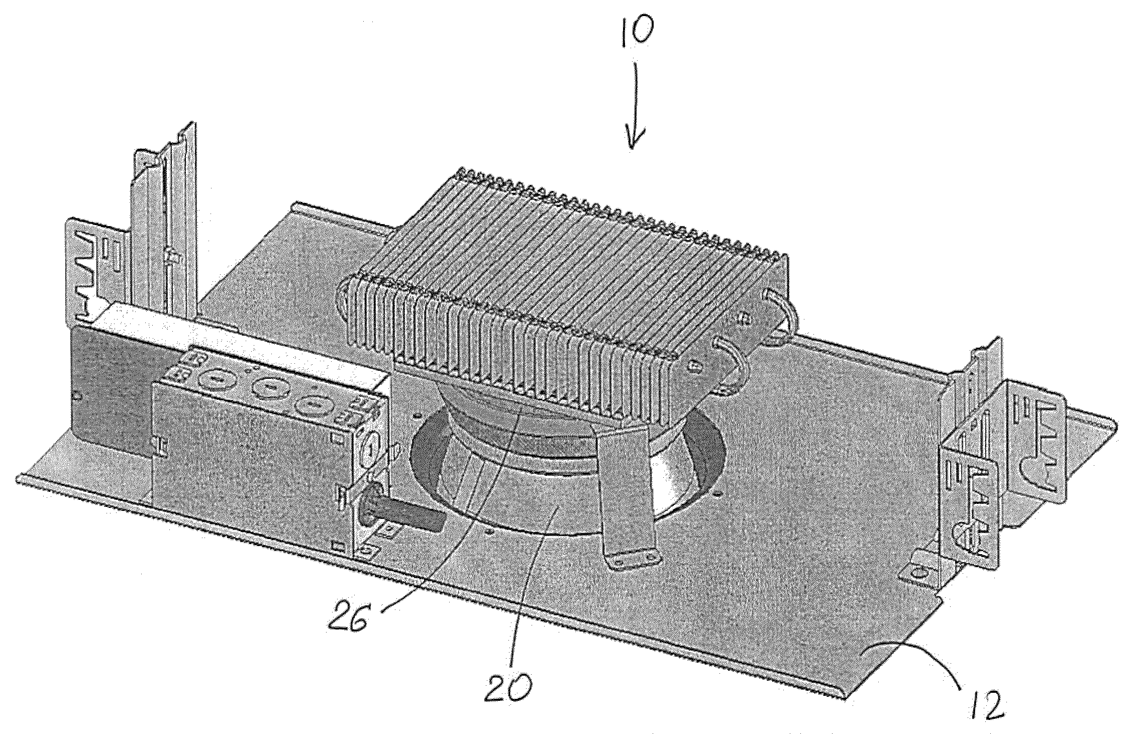
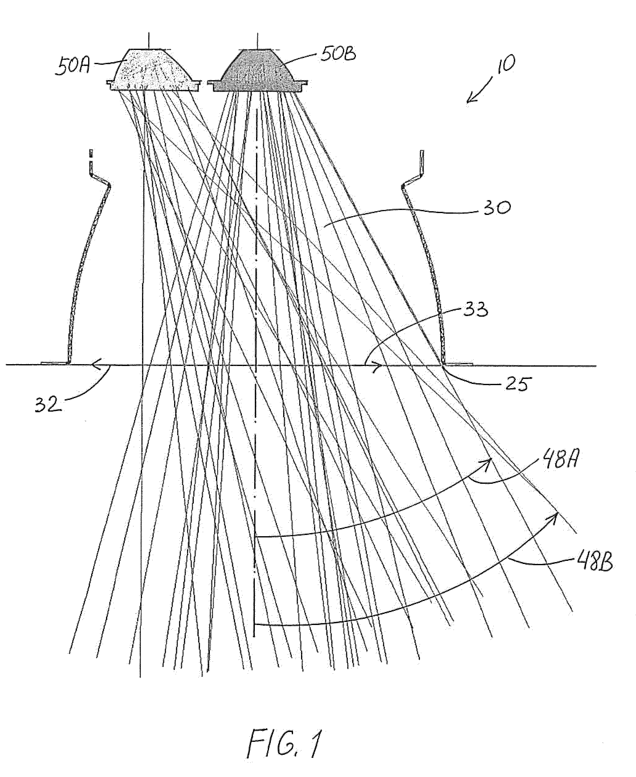
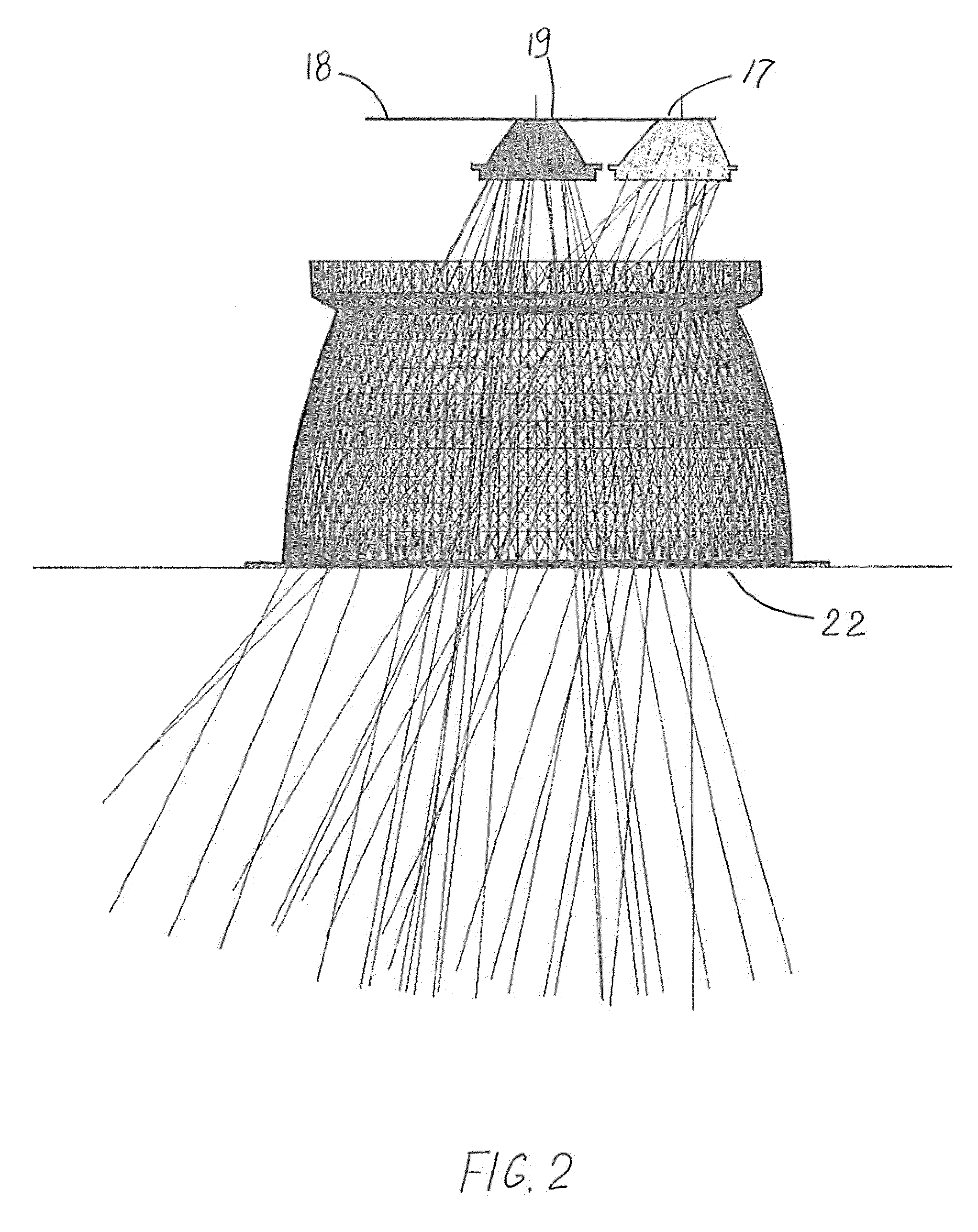
[0052]FIGS. 1-10 illustrate preferred embodiments of the recessed lighting fixture 10 for mounting into a structure 12 facing an illumination area 14. Lighting fixture 10 includes a support member 20 configured for mounting into structure 12. Support member includes a front end-portion 22 having an edge 24 defining a light opening 16 and a back end-portion 26 recessed from opening 16. Support member 20 and opening 16 have a centerline 28. Lighting fixture 10 further includes a mounting board 18 with an LED arrangement 40 including LED emitters 42 on mounting board 18 for directing light 46 toward opening 16 and a lens 50 for each emitter 42. Mounting board 18 is disposed at back end-portion 26 and together with support member 20 defines an open space 30 extending to opening 16. Each emitter 42 defines an emitter axis 44. At least one of emitters 42 is off-centerline in a first lateral direction 32 and has its associated lens 50A configured for distribution of light from emitter 42 i...


PUM


Abstract

A recessed lighting fixture for mounting into a structure (being an illumination area. The fixture includes a support member configured for mounting into the structure and including a front end-portion having an edge defining a light opening and a back end-portion recessed from the opening. The support member and opening have a centerline. A mounting board is disposed at the back end-portion and defines with the support member an open space extending to the opening. An LED arrangement includes (a) LED emitter(s) on the mounting board for directing light toward the opening, each emitter defining an emitter axis, and (b) a lens for each emitter at least one of which is off-centerline in a first lateral direction. The lens is configured for distribution of emitter light in off-axial direction across the open space and passing through the opening at an edge portion that is off-centerline in the opposite lateral direction, thereby to widen the illumination angle from the fixture while having no more than minimal light directed onto the support member.

Description

RELATED APPLICATION[0001]This application is based in part on U.S. Provisional Application Ser. No. 61 / 055,958, filed May 23, 2008, the contents of which ate incorporated herein by reference. This application also relates to U.S. application Ser. No. 12 / 173,721, filed Jul. 15, 2008, the contents of which arc incorporated herein by reference.FIELD Of THE INVENTION[0002]This invention relates to lighting fixtures and, more particularly, to recessed fixtures using LEDs.BACKGROUND OF THE INVENTION[0003]In recent years, the use of light-emitting diodes (LEDs) for various common lighting purposes has increased, and this trend has accelerated as advances have been made in LEDs and in LED-array bearing devices, often referred to as “LED modules.” Indeed, lighting applications which have been served by fixtures using high-intensity discharge (HID) lamps and other light sources are now increasingly beginning to be served by LED modules. Such lighting applications include, among a good many ot...

Claims


Application Information

Patent Timeline
Patent Type & Authority Applications(United States)
IPC IPC(8): F21V15/00
CPCF21S8/02F21V5/08G02B19/0061F21Y2101/02G02B19/0028F21V7/0091F21Y2105/10F21Y2115/10
Inventor RUUD, ALAN J.WILCOX, KURT S.CASTILLO, MARIO ALBERTO
Owner IDEAL IND LIGHTING LLC
Why Eureka
Try Eureka