
Jewelry Item Having Reduced Weight and Enhanced Strength

Inactive Publication Date: 2009-12-03
STULLER MFG
View PDF23 Cites 8 Cited by
  • Summary
  • Abstract
  • Description
  • Claims
  • Application Information

AI Technical Summary

Benefits of technology

[0008]It is an object of the invention to provide a method of manufacturing jewelry in which the amount of precious metal required may be reduced.
[0009]It is another object of the invention to provide a method of manufacturing jewelry with reduced precious metal content while enhancing the strength of the jewelry piece.
[0010]It is still another object of the invention to provide a hollow precious metal jewelry piece with enhanced strength.
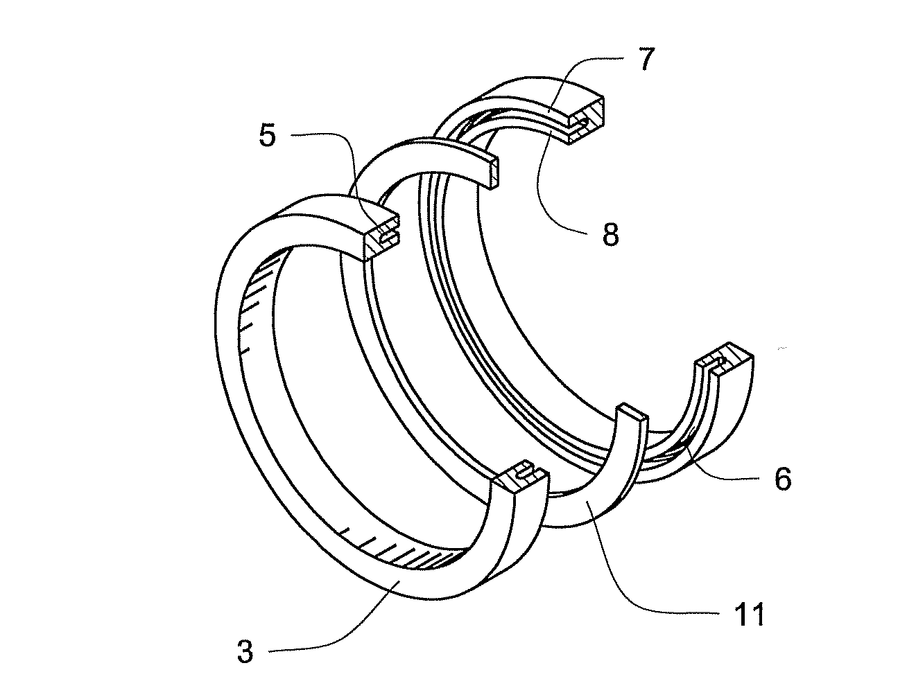
[0013]The central section will preferably be formed of the same precious metal as the left and right sections. Once the three components are joined together, the resultant piece may be machined and polished to both achieve the desired finished shape and to eliminate any visible seams between the sections. Using common components for all three sections will enhance this objective. However, it will be appreciated that different materials may be used for any of the sections if contrast is desired for cosmetic and / or structural purposes.

Problems solved by technology

However, all of the foregoing approaches have disadvantages.
In plated jewelry, the plating can wear away, exposing the substrate.
This is obviously undesirable and is considered by many wearers to be cosmetically unacceptable, such that a piece in which the plating has worn away to the point where the substrate is exposed, even in a small area, will no longer be considered wearable.
This is a problem with all plated jewelry, but is a particular concern with high wear pieces such as rings.
Pieces that include divots and hollow jewelry share a common disadvantage.
A piece with excessive divots may be easily dented if the piece is impacted.
Such damage is a concern with all divoted or hollow jewelry, but is a particular problem with high wear pieces such as rings.

Method used


Image

  • Jewelry Item Having Reduced Weight and Enhanced Strength
  • Jewelry Item Having Reduced Weight and Enhanced Strength
  • Jewelry Item Having Reduced Weight and Enhanced Strength

Examples


Embodiment Construction

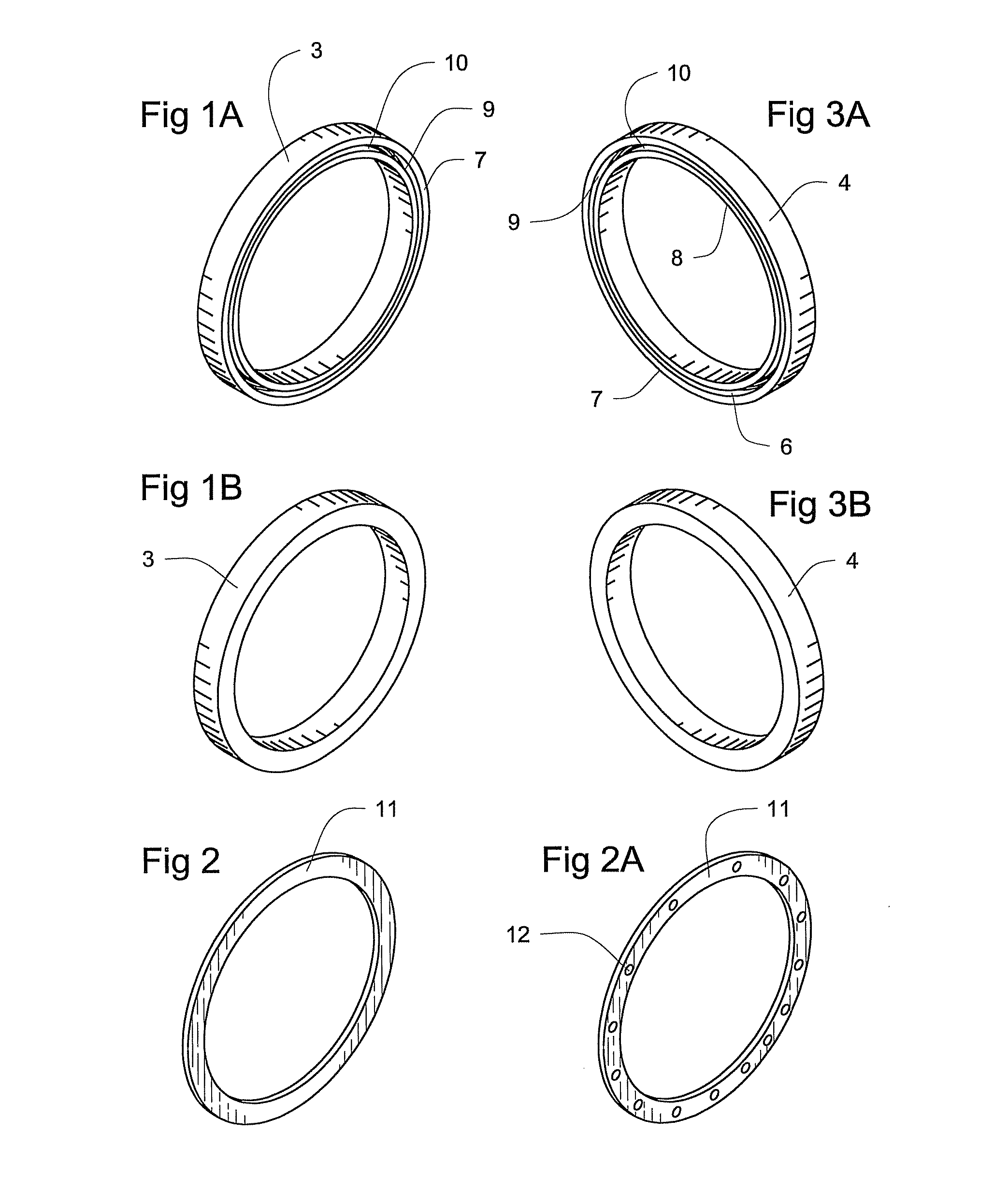
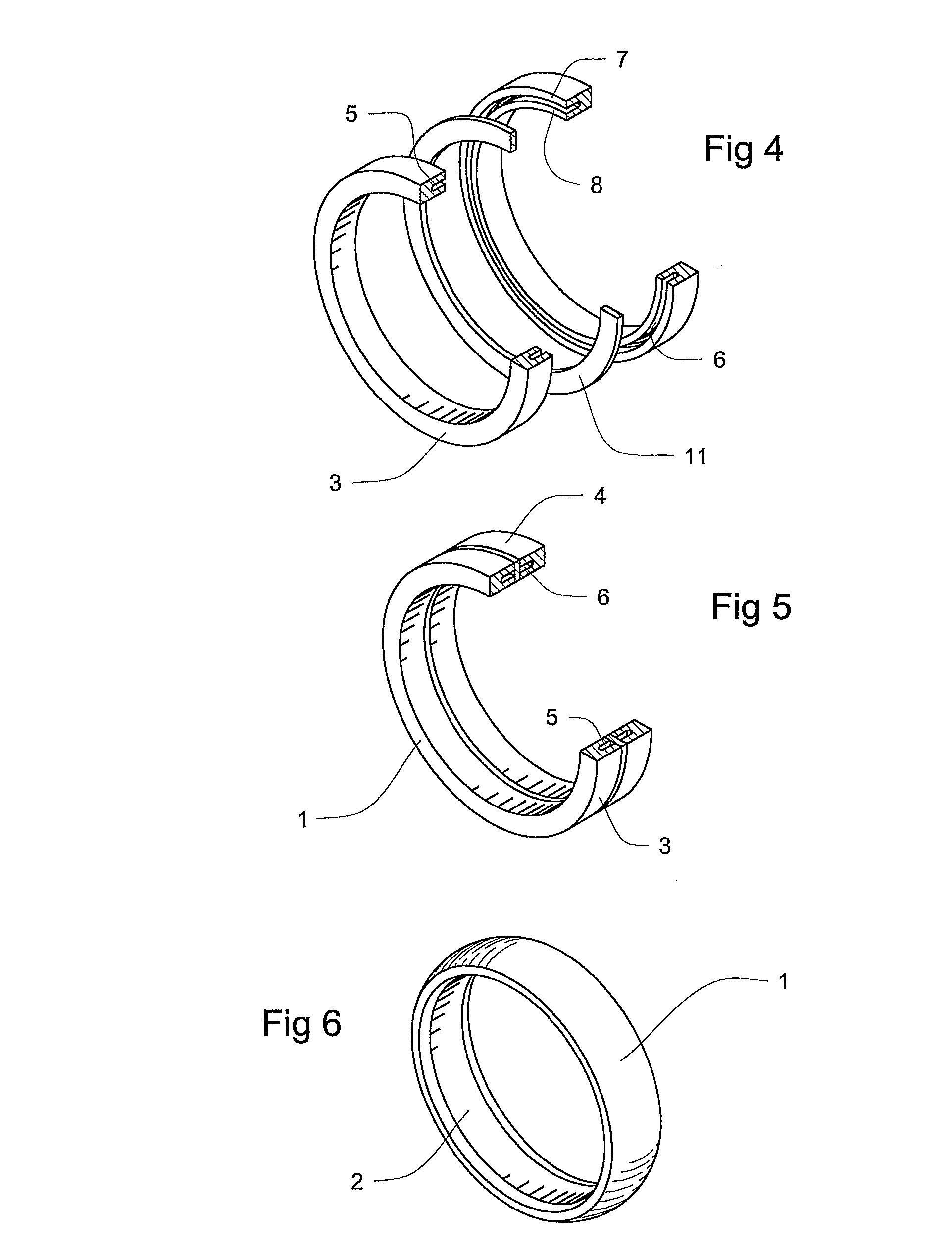
[0023]A reduced weight jewelry piece 1 is disclosed. It will be appreciated that jewelry piece 1 may be any conventional jewelry item, such as brooches, pendants, earrings, chain links, and so forth. However, in the most preferred embodiment, jewelry piece 1 is a ring 2.

[0024]In the preferred embodiment, jewelry piece 1 is comprised of a left section 3 and a right section 4. Left section 3 and right section 4 are preferably mirror images of each other. Each section 3, 4 is preferably provided with a hollow channel 5, 6. Channels 5, 6 will preferably run the length or circumference of each section 3, 4. Each channel 5, 6 has an exterior wall 7 and an interior wall 8. Exterior wall 7 will face the surface of jewelry piece 1 and interior wall 8 will face the side of jewelry piece 1 adjacent the wearer. However, it will be appreciated that for some jewelry pieces, such as hoop earrings or chain links, there will be no distinction between the surfaces of the jewelry piece and thus, no di...


PUM


Abstract

A reduced weight enhanced strength jewelry piece. In the preferred embodiment, the piece is comprised of a left section and a right section, each preferably containing a substantially hollow channel. A central section is also provided. All three sections are preferably formed of the same precious metal, though different metals could be used if contrast is desired in the finished piece. In the preferred embodiment, the central section is a substantially solid piece fitted to match both the left section and the right section. The three sections are joined together to form a jewelry piece. The resultant jewelry piece will have two substantially hollow chambers transected by a substantially solid piece. The substantially solid piece will serve as a brace to the hollow chambers, such that if a force were applied to the jewelry piece transverse to the hollow chambers of the piece, the central section would resist deformation.

Description

BACKGROUND OF THE INVENTION[0001]1. Field of the Invention[0002]The invention relates to precious metal jewelry in general and to hollow precious metal jewelry in particular.[0003]2. Prior Art[0004]It is well known in the jewelry industry to take steps to reduce the amount of precious metal utilized in the manufacture of various items of jewelry. Principally, this is done to reduce the expense of the piece and thereby either increase the profit margin of the jeweler, allow the piece to be sold at a lower price, or some combination of the two. Some examples of common steps taken to reduce the amount of precious metal required to manufacture jewelry include plating non-precious (or less precious) substrates with precious metal; including divots on the non-visible or interior side of the piece in order to reduce the thickness of the piece, and constructing the piece of hollow components. However, all of the foregoing approaches have disadvantages.[0005]In plated jewelry, the plating ca...

Claims


Application Information

Patent Timeline
IPC IPC(8): A44C5/00
CPCA44C9/0015
Inventor WEBB, H. JAMES
Owner STULLER MFG
Learn More