
Steam shower having improved maintenance access

a technology of shower and maintenance access, which is applied in the direction of dryer section, textiles and papermaking, paper-making, etc., can solve the problems of unnecessarily increasing the weight of the components that have been moved, and the 534 patent may not be desirable for some applications

Inactive Publication Date: 2009-12-03
ABB LTD
View PDF1 Cites 5 Cited by
  • Summary
  • Abstract
  • Description
  • Claims
  • Application Information

AI Technical Summary

Problems solved by technology

'534 patent may not desirable for some applications.
Since the access slots are narrow and located at the bottom of the screen, the steam shower of the Passiniemi publication appears to provide only limited access to the steam diffusers.
While the steam shower of EP1310591A2 provides access to both the steam diffusers and the steam valve modules, the steam shower requires the main steam header to be moved along with the steam diffusers and the steam valve modules, which unnecessarily increases the weight of the components that have be moved to provide the access.

Method used


Image

  • Steam shower having improved maintenance access
  • Steam shower having improved maintenance access
  • Steam shower having improved maintenance access

Examples


second embodiment

[0046]Referring now to FIGS. 8 and 9, a second steam shower 200 constructed in accordance with the present invention is shown. The second steam shower 200 and the first steam shower 10 have a number of components that are identical and, thus, will share the same reference numerals, as generally noted at the beginning of the description section. For purposes of brevity, such identical components will not be described again with regard to the second steam shower 200.

[0047]The second steam shower 200 includes a crossbeam 210 that comprises a base structure 202, a shroud 204 and end plates 212 and 214 and a cover 238, each of which is formed from a metal, such as steel. The shroud 204 is secured to the base structure 202, such as by welding. The end plate 212 is secured (such as by welding) to the ends of base structure 202 and the shroud 204 on the tending side, while the end plate 214 is secured (such as by welding) to the ends of the base structure 202 and the shroud 204 on the drivi...

third embodiment

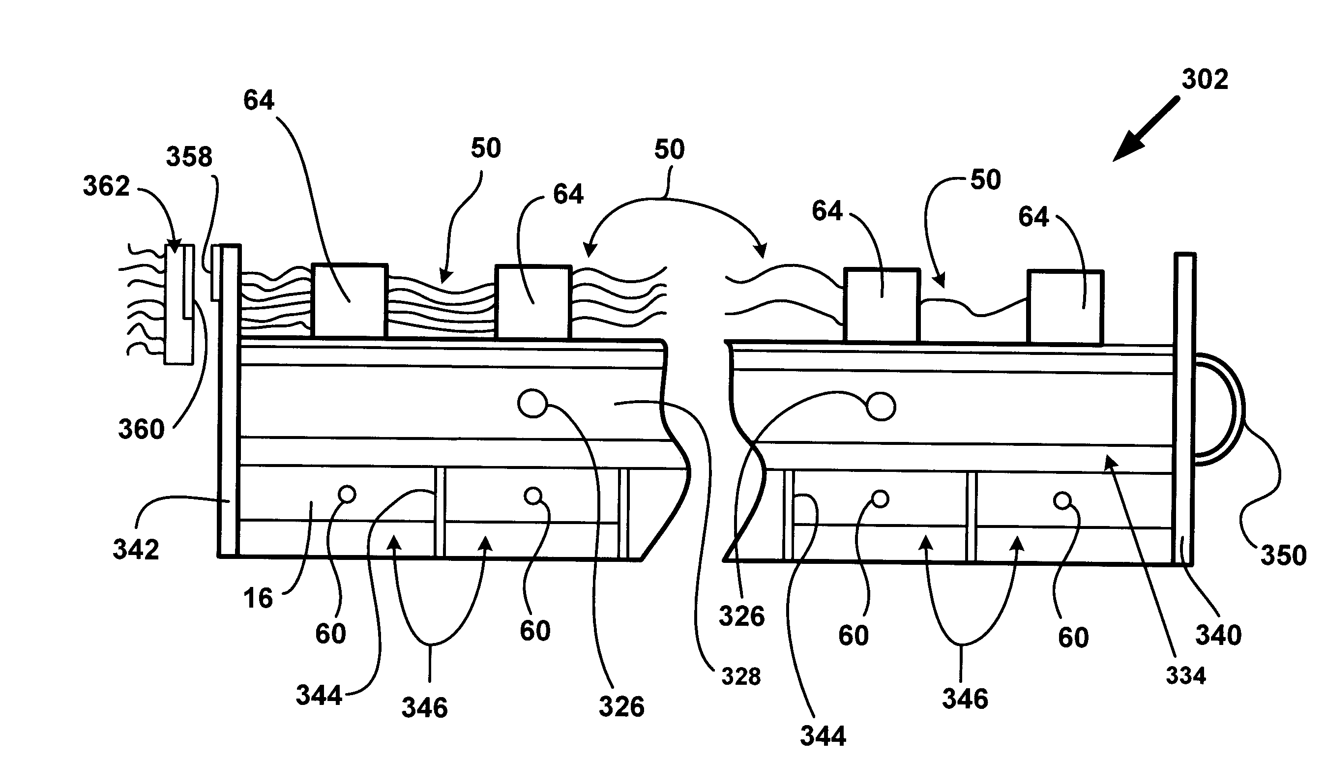
[0060]Referring now to FIGS. 10-12, there is shown a third steam shower 300 constructed in accordance with the present invention. The third steam shower 300 and the first steam shower 10 have a number of components that are identical and, thus, will share the same reference numerals, as generally noted at the beginning of the description section. For purposes of brevity, such identical components will not be described again with regard to the third steam shower 300. The third steam shower 300 generally includes a steam provision assembly 302 movably mounted to a cross-beam 304.

[0061]The cross-beam 304 includes a top section 306, a bottom section 308, and end plates 310, 312, each of which is composed of a metal, such as steel. The top and bottom sections 306, 308 are secured together, such as by longitudinal welds, and the end plates 310, 312 are secured to opposing ends of the thusly formed structure, respectively, such as by welding. When secured together in this manner, the top a...


PUM


Abstract

A steam shower is provided for supplying steam to a web in a paper machine. The steam shower includes a diffuser assembly mounted to the cross-beam for movement in the direction of the longitudinal axis of the cross beam. The cross-beam defines an interior steam header for connection to a source of steam. The diffuser assembly includes a plurality of separated steam compartments. The diffuser assembly may be part of a steam provision assembly that is also mounted to the cross-beam for movement in the direction of the longitudinal axis of the cross beam. In addition to the diffuser assembly, the steam provision assembly includes a second steam header and steam valve modules.

Description

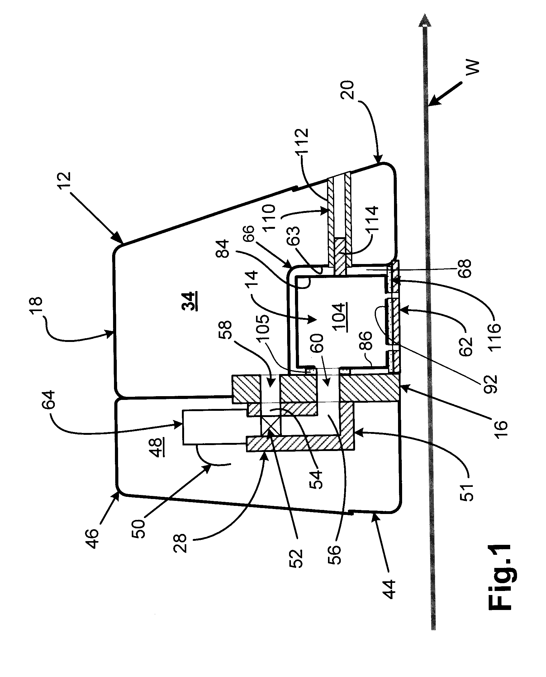
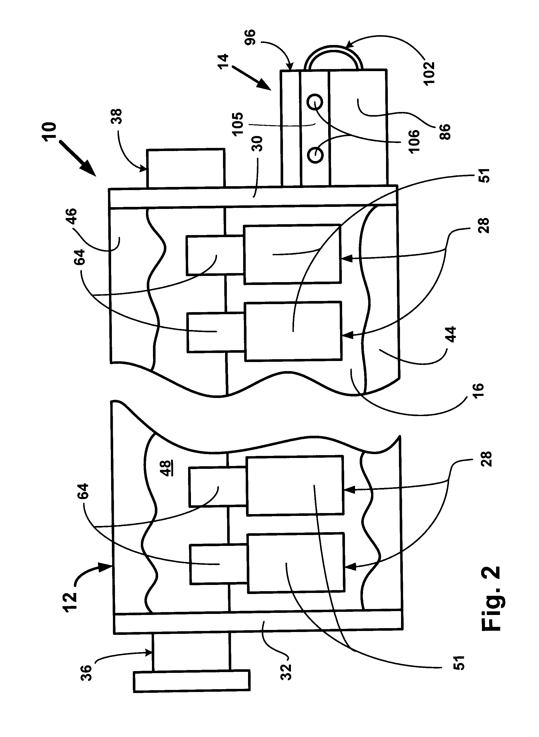
CROSS-REFERENCE TO RELATED APPLICATION[0001]This application claims the benefit of U.S. provisional patent application No. 61 / 057,840 filed on May 31, 2008, which is hereby incorporated by reference in its entirety.BACKGROUND OF THE INVENTION[0002]This invention relates to steam showers and more particularly to a steam shower having an improved construction that facilitates maintenance.[0003]Steam showers are widely used on paper machines to improve the operation of the machines as well as to improve the moisture profile of the paper products produced thereby. When steam contacts the cold surface of a moving paper web, it condenses into water. During the condensation, latent heat is released from the steam and absorbed by the moving web. With the absorption of the latent heat, the temperature of the moving web increases and therefore the tension inside the moving web decreases. Reduction of the tension inside the web allows the paper machine to run at a higher speed without breaking...

Claims


Application Information

Patent Timeline
IPC IPC(8): D21G9/00
CPCY10S162/06D21F7/008
Inventor SPACHMAN, JOHNDUAN, SHIZHONG S.DOERSCHUK, DAVIDDURCAN, PAUL
Owner ABB LTD
Learn More