Apparatus and method for blending fluids

Active Publication Date: 2009-12-03
GLOBAL GROUND SUPPORT
View PDF17 Cites 8 Cited by
  • Summary
  • Abstract
  • Description
  • Claims
  • Application Information

AI Technical Summary

Benefits of technology

[0017]Next, the step of manipulating the blended fluid includes adjusting the composition of the blended fluid by incorporating additional fluid from one of the first or second tanks into the blend tank to achieve the target fluid composition. To ensure proper deicing, the method also provides for heating the blended fluid prior to application.
[0018]In a novel aspect, the method further provides the step of purging the existing processed blended fluid from the blend tank, the heater, and a device for applying the processed heated blended fluid (e.g., a boom). The purge step is accomplished when the apparatus is shut-down for storage during n

Problems solved by technology

In freezing conditions, there exists a danger that ice may form on the surfaces of an aircraft.
Because the principle of flight with respect to modern aircraft is based on the smooth flow of air over the surfaces of the aircraft to generate lift, any ice that accumulates on the surface can degrade the aircraft's ability to fly by effectively roughening these surfaces.
Additionally, large pieces of ice that become dislodged from the surface can potentially damage propellers or turbine engines.
Further, thick ice can prevent the operation of the aircraft's controls (e.g., flaps and rudder).
Although this change in the freezing point would effectively melt any ice or prevent ice from forming, the use of pure glycol compositions in this way is excessive on all but the coldest of days and leads to waste of the glycol.
Thus, even with the glycol diluted in this fashion, an excessive amount of glycol may still be consumed.
Unfortunately, airline operators cannot simply use a weaker blend of glycol and water (e.g., a 20% glycol solution with a freezing point of about −8° C.) because weather conditions—and specifically the ambient temperature of the environment—may prevent the diluted blend from sufficiently lowering the freezing point of the water.

Method used


Image

  • Apparatus and method for blending fluids
  • Apparatus and method for blending fluids
  • Apparatus and method for blending fluids

Examples


Embodiment Construction

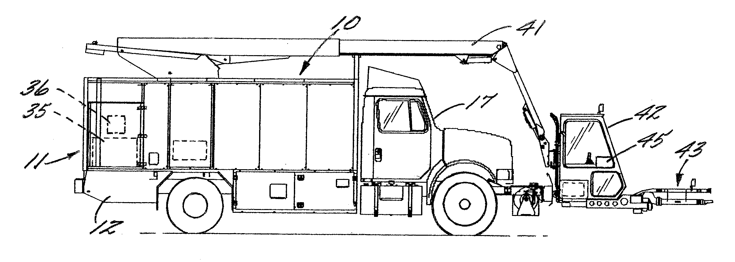
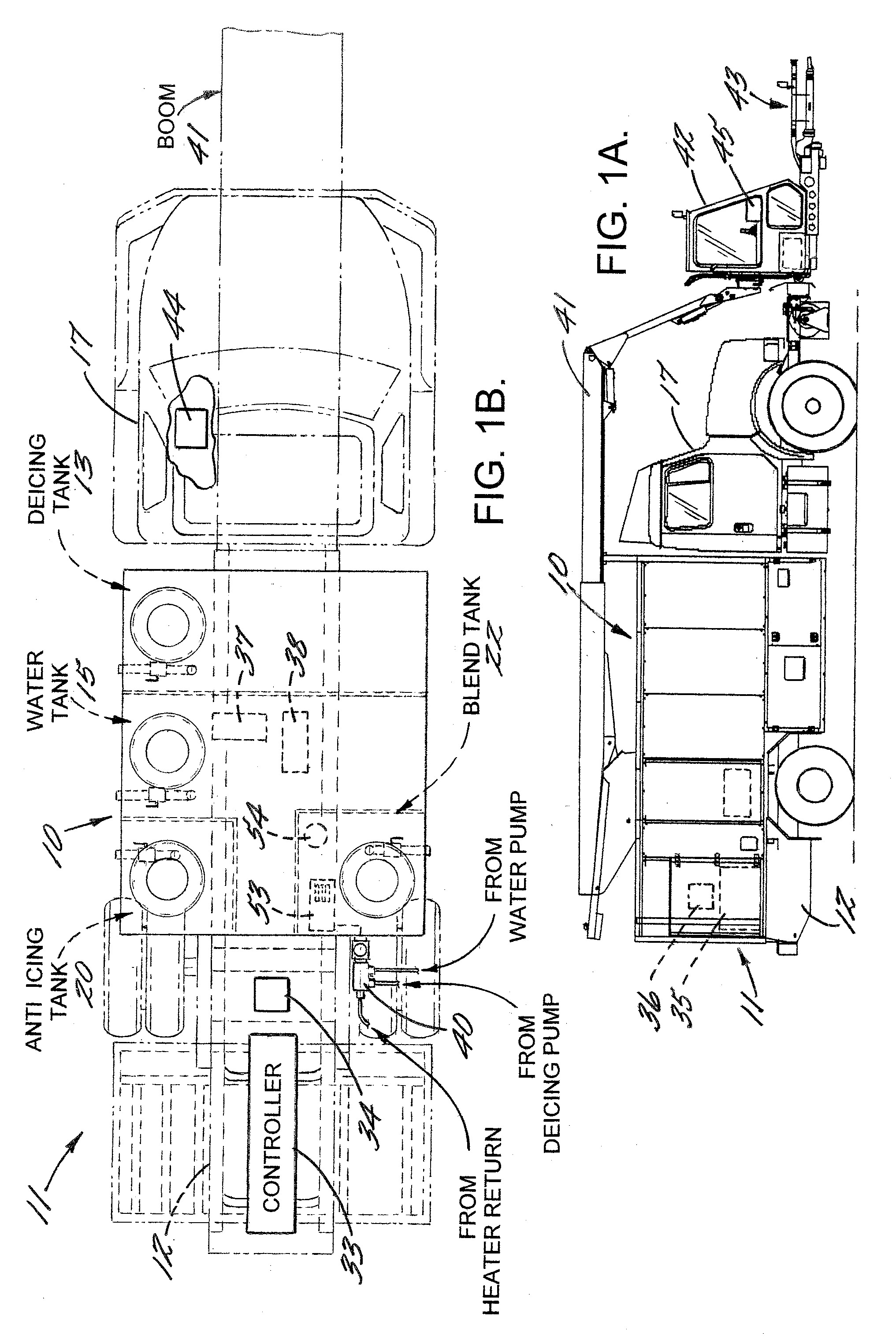
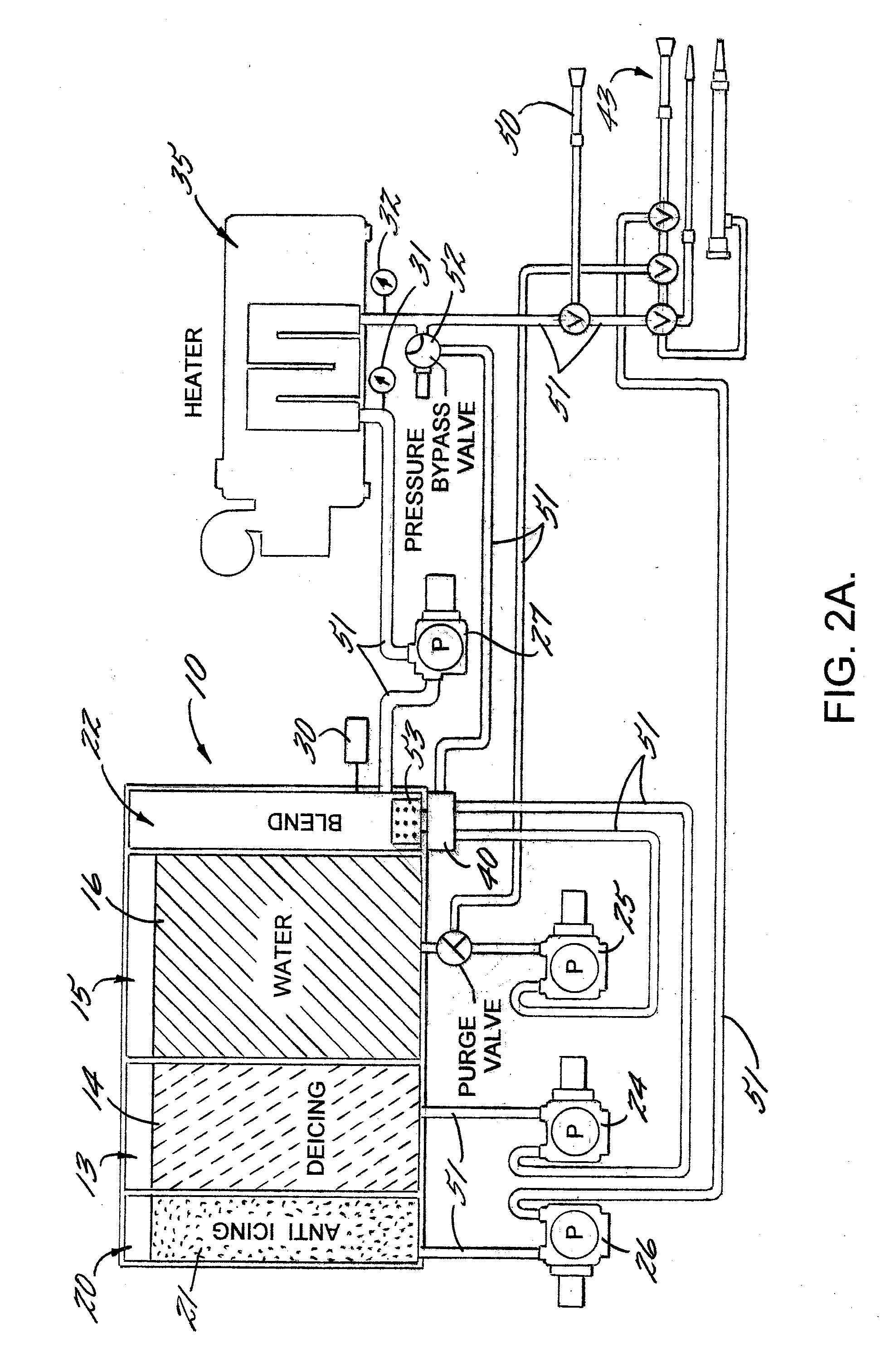
[0031]The invention will now be described more fully hereinafter with reference to the accompanying drawings, in which multiple embodiments of the invention are shown. This invention may, however, be embodied in different forms and should not be construed as limited to the embodiments set forth herein. Rather, these embodiments are provided so that this disclosure will be thorough and complete and will fully convey the scope of the invention to those skilled in the art. Like numbers refer to like elements throughout. Further, like numbers with the prime notation refer to like or similar elements of the structure.

[0032]An overall view of the apparatus 10 for blending fluids that incorporates features of the present invention is set forth in FIGS. 1A and 1B. As depicted in FIG. 1B, the apparatus 10 includes a first tank 13 containing a first fluid 14, a second tank 15 containing a second fluid 16, a third tank 20 containing a third fluid 21, and a blend tank 22 in fluid communication ...


PUM


Abstract

An apparatus and method for blending fluids and applying the blended fluid to a surface of an aircraft during deicing and anti-icing operations having a first tank, second tank, blend tank, pumps, conduits, heaters, controllers, and a delivery device. In operation, a controller compares the composition of the blended fluid in the blend tank to the composition of a target fluid that is determined by current ambient temperature of the environment, and advances first and second fluids from the first and second tanks, respectively, into the blend tank to achieve and maintain the target fluid composition in the blend tank.

Description

FIELD OF THE INVENTION[0001]The invention relates to equipment for blending fluids and applying the blended fluid to a surface. Specifically, the invention relates to an apparatus for creating a blend of deicing fluid and water to create a deicing solution for use on aircraft or other vehicles, wherein the composition of the blended solution is tailored to current weather conditions. The invention further relates to a method for applying the blended fluid to an aircraft.BACKGROUND[0002]In freezing conditions, there exists a danger that ice may form on the surfaces of an aircraft. Because the principle of flight with respect to modern aircraft is based on the smooth flow of air over the surfaces of the aircraft to generate lift, any ice that accumulates on the surface can degrade the aircraft's ability to fly by effectively roughening these surfaces. Additionally, large pieces of ice that become dislodged from the surface can potentially damage propellers or turbine engines. Further,...

Claims


Application Information

Patent Timeline
IPC IPC(8): B64D15/10B64F5/00B05B1/24B05B7/26B60P3/30
CPCG05D11/139B64F5/0063B64F5/23Y10T137/1963
Inventor SMITH, RICHARD L.
Owner GLOBAL GROUND SUPPORT
Why Eureka
Try Eureka