[0007]In view of the above, according to the armrest apparatus of the present invention, which uses the spring lock effect of a coil spring with a simple constitution, a coil spring has an inner diameter that is larger than the outer diameter of a fixed shaft and is wound around the shaft in a state that the arm-rest member is able to turn freely upward and downward with respect to the drum (hereafter called a loosely-fitting state). With this structure, in the present invention, when the armrest is rotated downward to its use position, the rotation of the coil spring is restricted, and a tightening force is generated on the coil spring by the downward load provided by the arm-rest member at this time, so that the coil spring can provide a locking force. Thus, the present invention us based on an idea completely different from the conventional ideas, and the present invention is able to make the armrest apparatus lighter, make the overall size smaller and make the manufacturing cost lower.
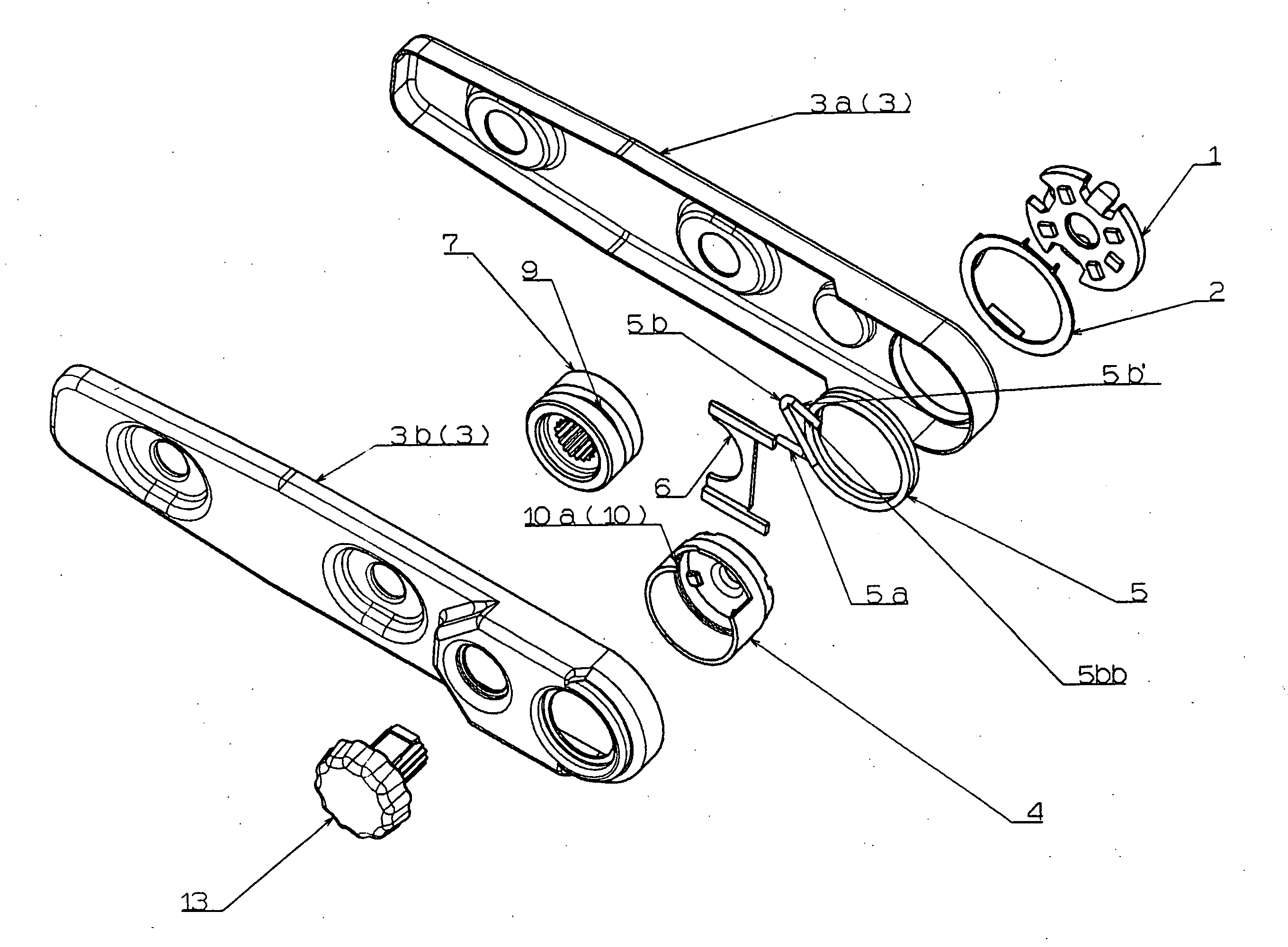
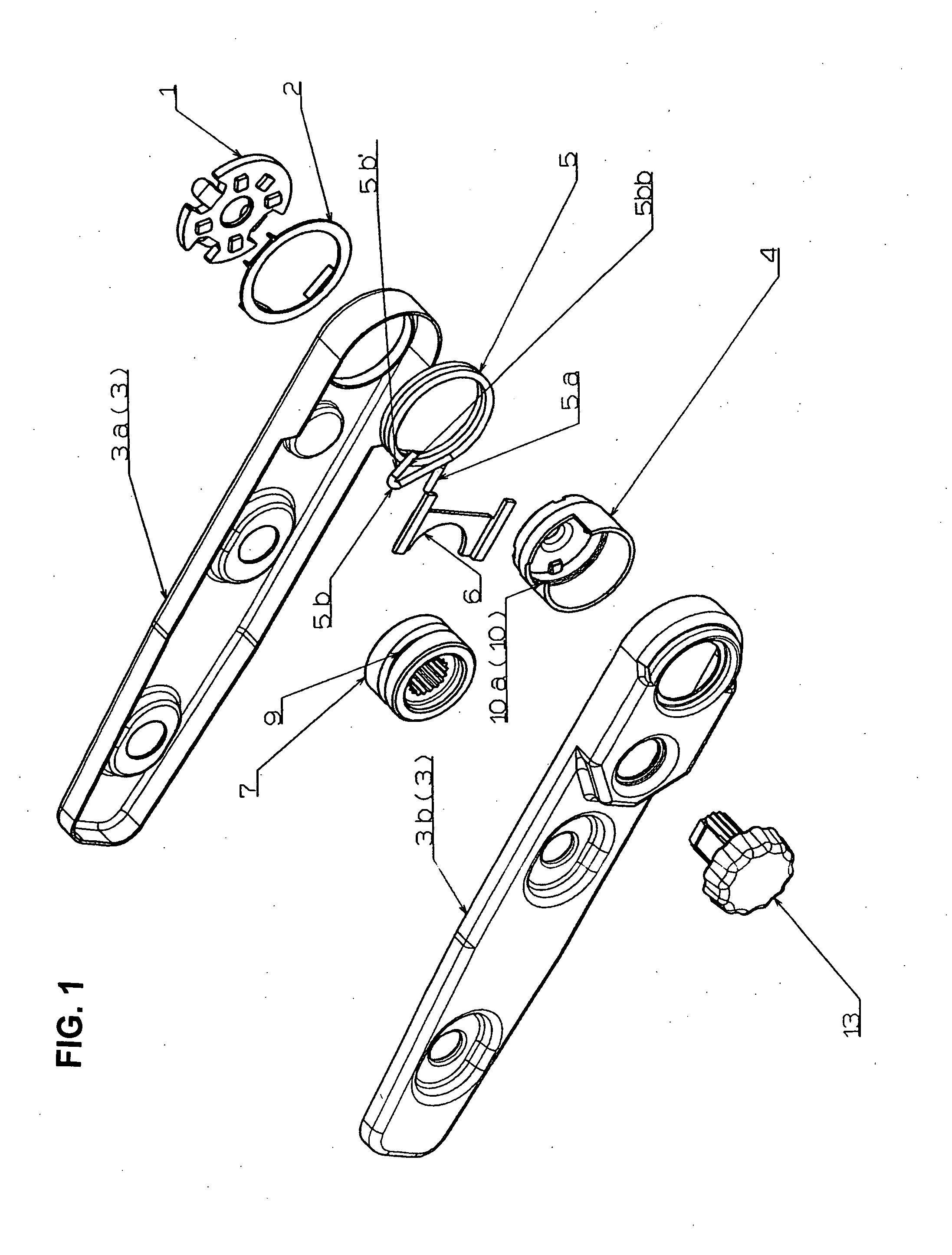
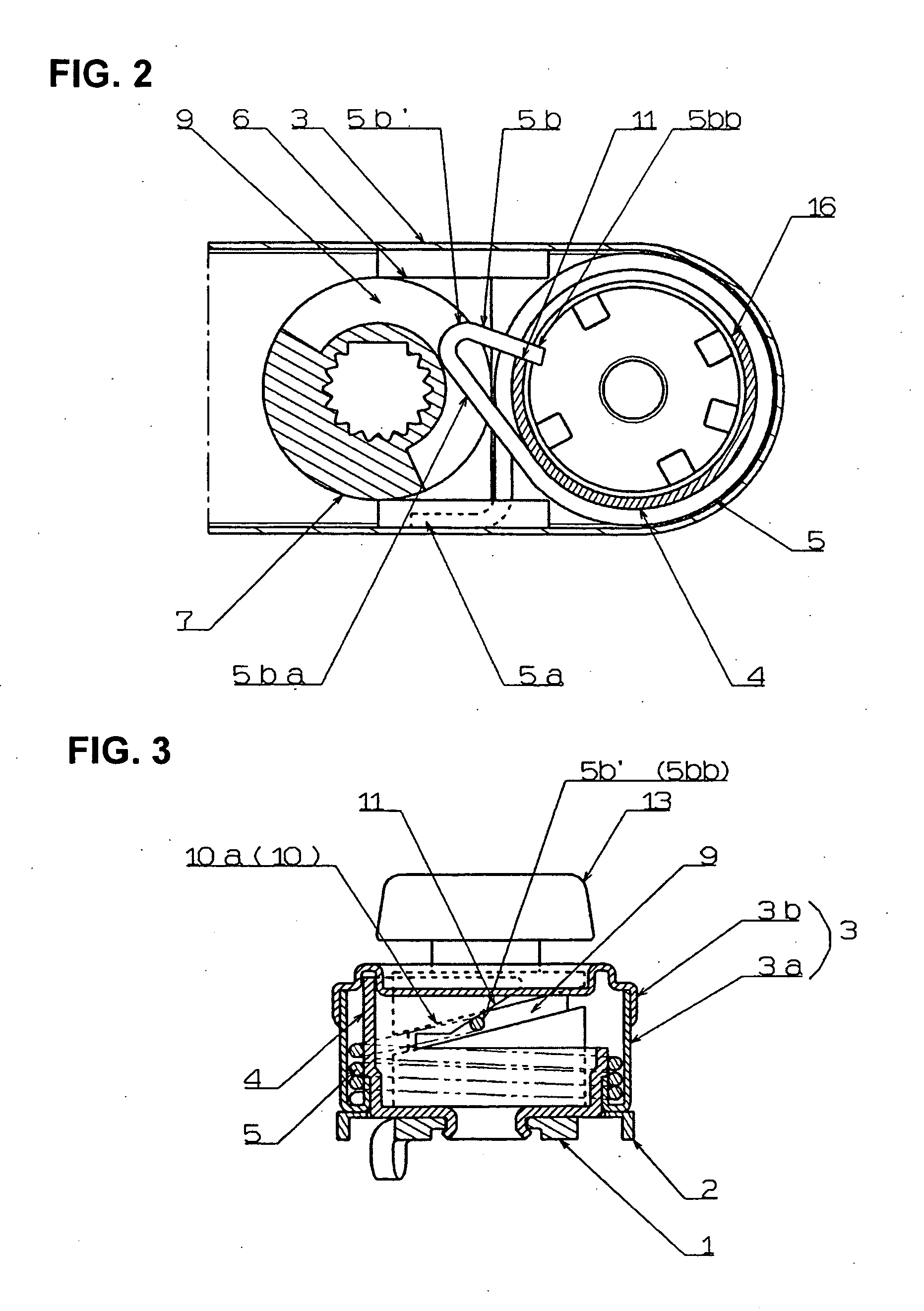
[0011]when the arm-rest member is rotated downward and reaches the predetermined set angle, the coil spring tightens the drum by a downward load applied by the arm with the coil end receiving surface being in contact with the curved part of the coil spring, thus restricting downward rotation of the arm beyond the predetermined set angle.
[0012]Furthermore, in the armrest apparatus of the present invention, the coil end receiving surface is formed to be an inclined surface inclined with respect to the axial direction of the drum, so that with use of an operating member, the curved part of the coil spring is moved in the axial direction of the drum, allowing the predetermined set angle at which the downward rotation of the arm-rest member is restricted to be changed freely.
[0013]In addition, in the armrest apparatus of the present invention, the coil end receiving surface of the drum can be a parallel surface formed in parallel to an axial direction of the drum, so that with use of an operating member, the curved part of the coil spring is moved in a circumferential direction of the drum, allowing the predetermined set angle at which the downward rotation of the arm-rest member is restricted to be changed freely.
[0016]As seen from the above, according to the present invention, the restriction of the downward turning of the coil spring, specifically, the restricting of the downward rotation of the arm-rest member when the arm-rest member reaches the set angle, can be made by a simple structure in which a curved part is formed on the free end side of the coil spring and a coil end receiving surface for receiving this curved part is formed on the drum, and thus a release mechanism and return mechanism required in the conventional armrest apparatus are not required in the present invention. In the structure of the present invention, the restriction force that restricts the downward turning of the coil spring (or the arm-rest member) is the tightening force of the coil spring which is generated when the coil spring is tightened on the entire outer surface of the drum; and when the coil spring is tightened, the free end side of the coil spring is received by the coil end receiving surface of the drum and the free end is prevented from slipping; accordingly, it is possible to counteract this with force that is applied until the wire is pulled and broken, and this restriction force is extremely strong. As a result, it is not necessary to make various considerations for the cross-sectional shape of the wire used for the coil spring, and it is also possible for the coil spring to have low number of turning (the minimum turning number for winding the entire circumference of the drum would be three (three turns)). Also, since there are no variations in the magnitude of the restriction force in terms of the dimension precision of the coil's inner diameter, production is easy, smaller size and lighter weight are possible, and productivity is excellent (lowering the cost).
[0017]Furthermore, in the structure of the armrest apparatus of the present invention, what restricts the downward rotation of the arm-rest member is the set angle that is set in advance; and above this set angle, it is possible to rotate freely upward and downward; it is, therefore, also possible to fold the arm-rest member upward and house it and to move it upward when it stands in the way, and it is possible to accurately return it to the originally set position when returning it. In addition, when the angle of the arm-rest member needs to be adjusted upon the change of the driver or upon the change in the seat position, such an angle adjustment of the arm-rest member can be made by changing the contacting point of the free end of the coil spring with respect to the coil end receiving surface of the drum. Thus, in the present invention, the changing constitution and the changing operation of the angle of the arm-rest member are simple.

