Circuit and topology for very high reliability power electronics system

a power electronics and circuit topology technology, applied in the field of circuit and system topology to provide a high reliability power system, can solve the problems of limiting the redundancy of power semiconductors, risk of non-redundant interface failure(s) between the control system and the power semiconductors, and inability to accept sub-sea power conversion systems

Inactive Publication Date: 2009-12-03
GENERAL ELECTRIC CO
View PDF4 Cites 26 Cited by
  • Summary
  • Abstract
  • Description
  • Claims
  • Application Information

AI Technical Summary

Benefits of technology

The invention relates to a power electronics system with multiple redundant components for use underwater or on land. This includes power converters and sub-sea power electronics modules which can operate even if there are failures within their respective control systems. By providing this redundancy, the system will always have sufficient capacity to meet its requirements no matter what kind of scenario it may face.

Problems solved by technology

The technical problem addressed in this patent is to improve the reliability of power systems, particularly in sub-sea power conversion systems, by eliminating any single point of failure associated with the power converter/power electronics system. This is achieved by designing a circuit/system that can fit easily within existing AC/DC converter topologies, DC/AC converter topologies, or DC/DC converter topologies and can be tested from time to time to ensure proper functionality.

Method used


Image

  • Circuit and topology for very high reliability power electronics system
  • Circuit and topology for very high reliability power electronics system
  • Circuit and topology for very high reliability power electronics system

Examples


Embodiment Construction

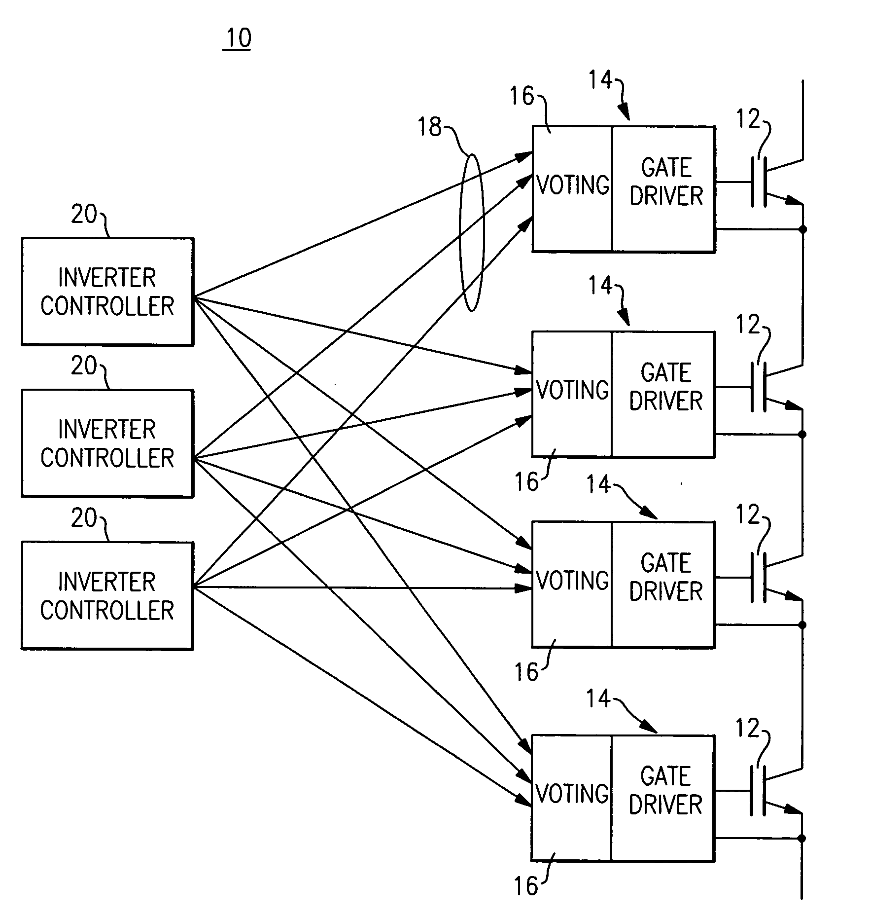
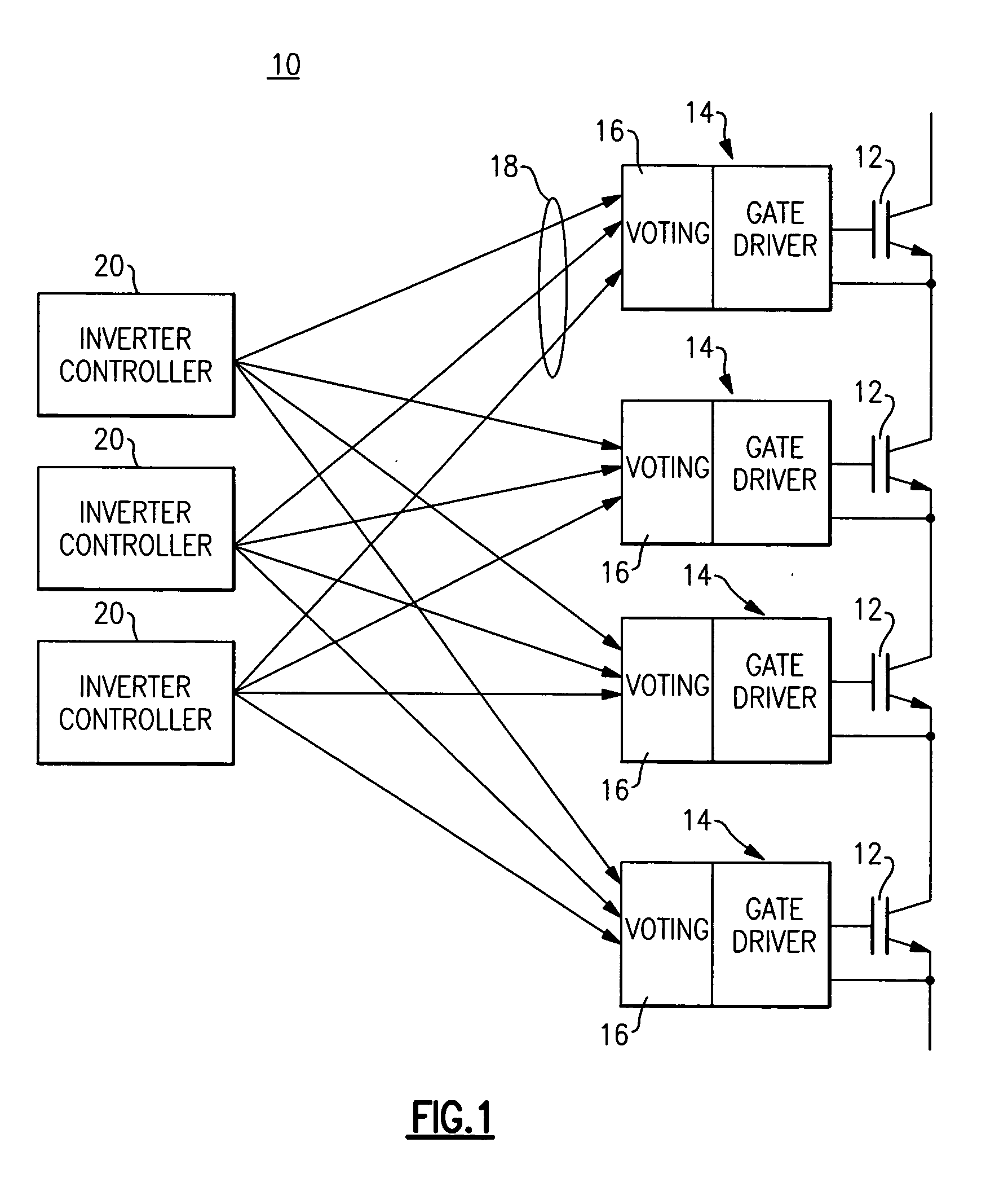
[0029]FIG. 1 illustrates a circuit and system topology for a high power electronics system with no single point of failure which is used as a basic building block for many different embodiments. The high power electronics system 10 serves as a single switch function and may be employed in almost every known power electronics topology. It includes a plurality (n+1) of substantially identical high power switching devices 12 such as, without limitation, power semiconductors connected in a series configuration to provide a desired level of switch redundancy such that the switch will continue to function following a short circuit failure mode of one or more of the switching devices 12. The power semiconductors can be, without limitation, IGBT or IGCT or thyristor devices.

[0030]The high power electronics system 10 provides a desired level of reliability / availability by extending the foregoing redundancy features also to the entire system. While a standard gate drive unit has only a single...


PUM


Abstract

A circuit and system topology includes a plurality of controller units configured to provide a high reliability power system. Sub-systems and devices are controlled via the plurality of controller units such that the high reliability power system remains functional, even subsequent to controller unit, sub-system and device failures.

Description


Claims


Application Information

Patent Timeline
Owner GENERAL ELECTRIC CO
Why Eureka
Try Eureka