Exit push rail monitoring system with hall effect sensor

a technology of push rail and sensor, which is applied in the direction of alarm locks, mechanical actuation of burglar alarms, instruments, etc., can solve the problems of product going into “error mode”, failure of the rail or pad of the device to remain in or return to the proper home position, and the end user that the product is no longer operational

Active Publication Date: 2017-11-14
SARGENT MANUFACTURING CO INC
View PDF8 Cites 9 Cited by
  • Summary
  • Abstract
  • Description
  • Claims
  • Application Information

AI Technical Summary

Benefits of technology

[0008]It is another object of the present invention to provide a delayed egress exit device which has enhanced reliability, and is less susceptible to errors due to problems in home positioning of the push rail or pad.
[0009]A further object of the invention is to provide a delayed egress exit device that remains in operation despite minor mis-positioning of the push pad or rail when released.
[0010]It is yet another object of the present invention to provide a delayed egress exit device that eliminates the need for frequent field adjustment, and automatically adjusts for changes in home position of the push pad or rail within predetermined limits.

Problems solved by technology

If the push rail or pad of the device does not remain in or return to the proper home position when released, even if only by a minor distance, the product goes into “error mode” alerting the end user that the product is no longer operational.
Failure of the rail or pad of the device to remain in or return to the proper home position may be caused by, mis-installation, tampering, blocking or worn-out components, and any other conditions that would influence the push rail or pad.

Method used


Image

  • Exit push rail monitoring system with hall effect sensor
  • Exit push rail monitoring system with hall effect sensor
  • Exit push rail monitoring system with hall effect sensor

Examples


Embodiment Construction

)

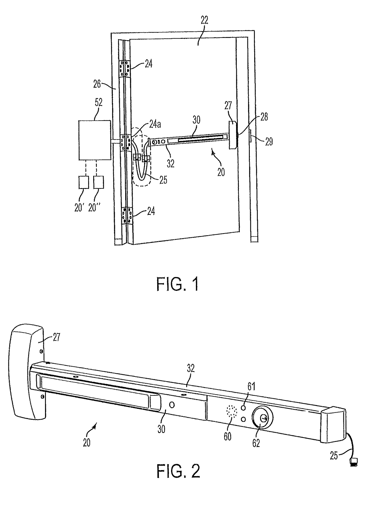
[0030]In describing the embodiments of the present invention, reference will be made herein to FIGS. 1-8 of the drawings in which like numerals refer to like features of the invention.

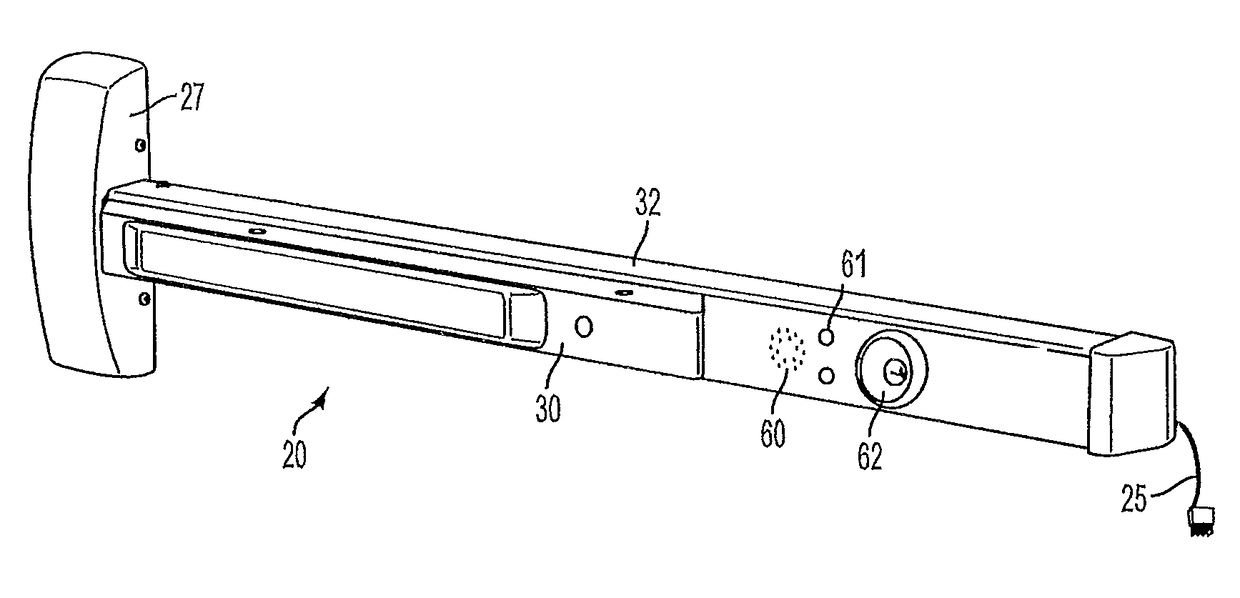
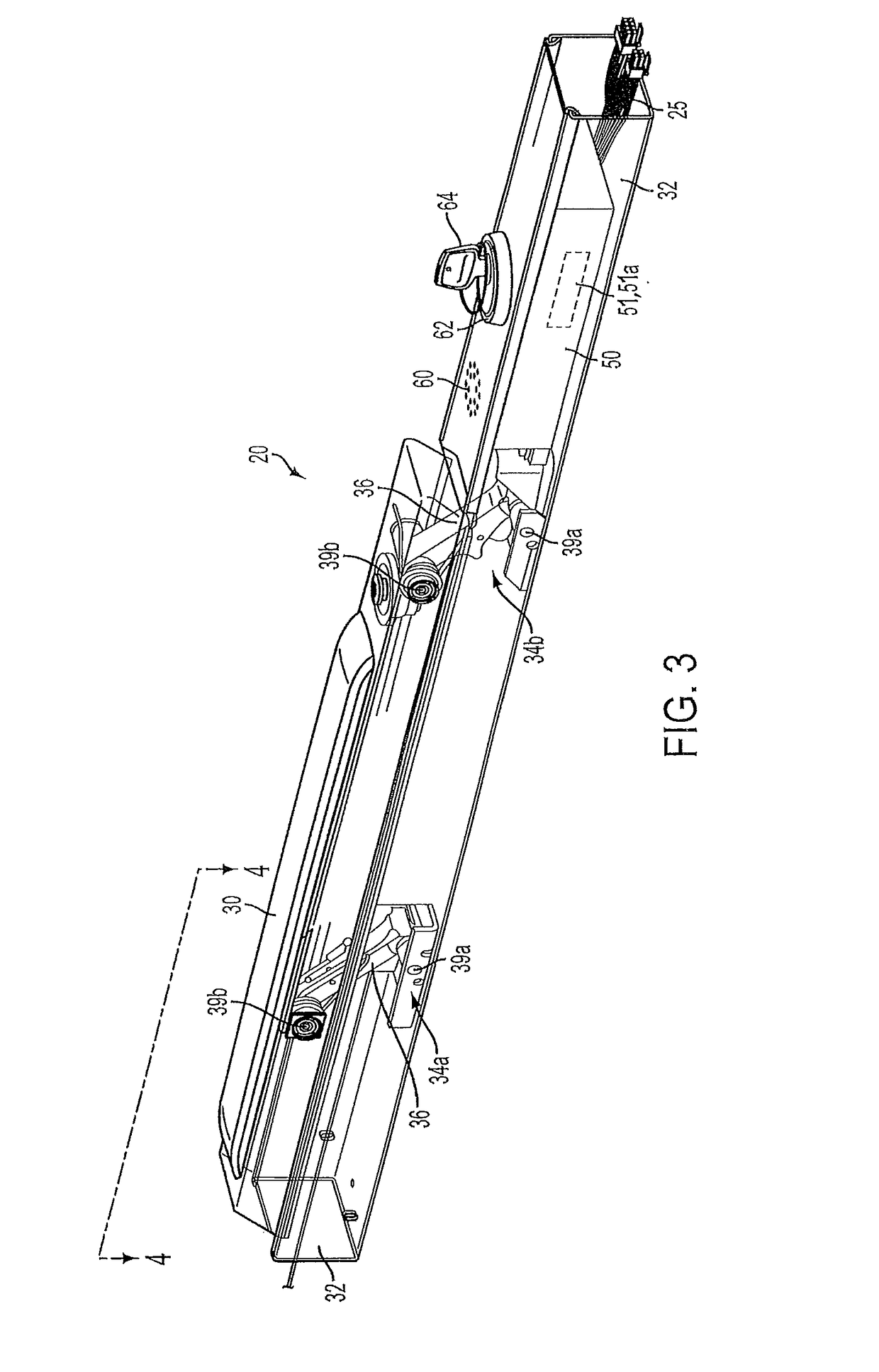
[0031]The present invention modifies the prior art delayed egress exit device and provides a monitoring feature which measures the position of the push rail or pad. Unless otherwise noted, the term rail shall also refer to a pad or other mechanism which is pushed by an individual user to attempt to exit though the door which the delayed exit device controls. The monitoring feature in one embodiment of the invention utilizes a magnet, an analog Hall effect sensor, and a microprocessor with firmware controlling the operation thereof. The push rail is monitored in real-time measuring any position differential off of or from the “home position,” which is the fully extended position. The magnet is disposed to move in conjunction with movement of the push rail. The analog Hall effect sensor is a transducer ...


PUM


Abstract

A delayed egress exit push rail system for a door has a push rail movable relative to a housing between a home position and a second position to open the door, a sensor for determining the position of the push rail as the push rail moves between the home position and the second position and a controller connected to the sensor. The sensor detects a current position of the push rail in the home position and the controller determines if the current position of the push rail detected by the sensor is within a predetermined acceptable range of positions relative to the home position. If the controller determines that the current position of the push rail is outside of the predetermined range, the controller unlocks the door for immediate egress, relays an error message via light or sound and / or communicates with a remote monitoring device.

Description

BACKGROUND OF THE INVENTION[0001]1. Field of the Invention[0002]This invention relates to door controls and in particular to doors employing push rails or pads which monitor attempts to egress through the door.[0003]2. Description of Related Art[0004]Delayed egress exit devices include a push rail or pad “request to exit” monitoring feature and are commonly used in schools, nursing homes, maternity wards, Alzheimer patient areas, psychiatric facilities, airports, shopping centers, libraries and other locations to provide a means of monitoring egress to prevent unauthorized exit through a door. When a delayed egress exit device is armed and the push rail or pad is depressed off of the normal home position, a monitoring feature within the device detects this movement and sounds a warning horn or alarm from the rail to alert personnel that someone is attempting egress. The sounding of the horn or alarm may be delayed to wait for the rail to remain depressed for a predetermined amount o...

Claims


Application Information

Patent Timeline
Patent Type & Authority Patents(United States)
IPC IPC(8): G08B13/08E05B65/10E05B43/00E05B47/00E05B45/06
CPCE05B47/00E05B43/005E05B45/06E05B65/1053E05B2047/0067E05B2045/0615E05B2047/0059E05B17/22E05B2047/0094E05B47/0038E05Y2400/44G01R15/202
Inventor WONG, WAI P.LIMONCELLI, JR., ARTHUR F.DEBIASE, DAVID C.NUNEZ, PAULLAWRENCE, III, EUGENE W.WALSH, JOHN E.ARCARIA, ANGELO S.
Owner SARGENT MANUFACTURING CO INC
Why Eureka
Try Eureka