Pacing system analyzer having three sensing and pacing channels

a pacing system and analyzer technology, applied in the field of pacing system analyzers, can solve the problems that the dual-chamber psa capable of sensing electrograms and delivering pacing pulses to two cardiac sites may not be able to accommodate desirable tests, and the programming of an implantable crm device has become an increasingly complicated task for healthcare professionals

Inactive Publication Date: 2009-12-03
DINGMAN PHILLIP +5
View PDF14 Cites 26 Cited by
  • Summary
  • Abstract
  • Description
  • Claims
  • Application Information

AI Technical Summary

Benefits of technology

[0006]In one embodiment, a PSA includes first, second, and third sensing and pacing channels, a pacing control circuit, a housing, and a user interface. The first, second, and third sensing and pacing channels each include a sensing circuit to sense a cardiac signal indicative of cardiac events and a pacing circuit to deliver pacing pulses. The pacing control circuit controls the delivery of the pacing pulses using a plurality of pacing parameters including user-programmable pacing parameters. The first, second, and third sensing and pacing channels and the pacing control circuit are enclosed in the housing. The user interface is electrically connected to the pacing control circuit and includes a pacing parameter input and a presentation device. The pacing parameter input allows programming of the user-programmable pacing parameters. The presentation device includes a display screen that displays the first, second, and third cardiac signals in real time.

Problems solved by technology

As a consequence, programming an implantable CRM device has become an increasingly complicated task for healthcare professionals.
A known dual-chamber PSA capable of sensing electrograms from and delivering pacing pulses to two cardiac sites may not be able to accommodate desirable tests preparing for the implantation of a tri-chamber pacemaker.

Method used


Image

  • Pacing system analyzer having three sensing and pacing channels
  • Pacing system analyzer having three sensing and pacing channels
  • Pacing system analyzer having three sensing and pacing channels

Examples


Embodiment Construction

[0022]In the following detailed description, reference is made to the accompanying drawings that form a part hereof, and in which is shown by way of illustration specific embodiments in which the invention may be practiced. These embodiments are described in sufficient detail to enable those skilled in the art to practice the invention, and it is to be understood that the embodiments may be combined, or that other embodiments may be utilized and that structural, logical and electrical changes may be made without departing from the spirit and scope of the present invention. The following detailed description provides examples, and the scope of the present invention is defined by the appended claims and their legal equivalents.

[0023]It should be noted that references to “an”, “one”, or “various” embodiments in this document are not necessarily to the same embodiment, and such references contemplate more than one embodiment.

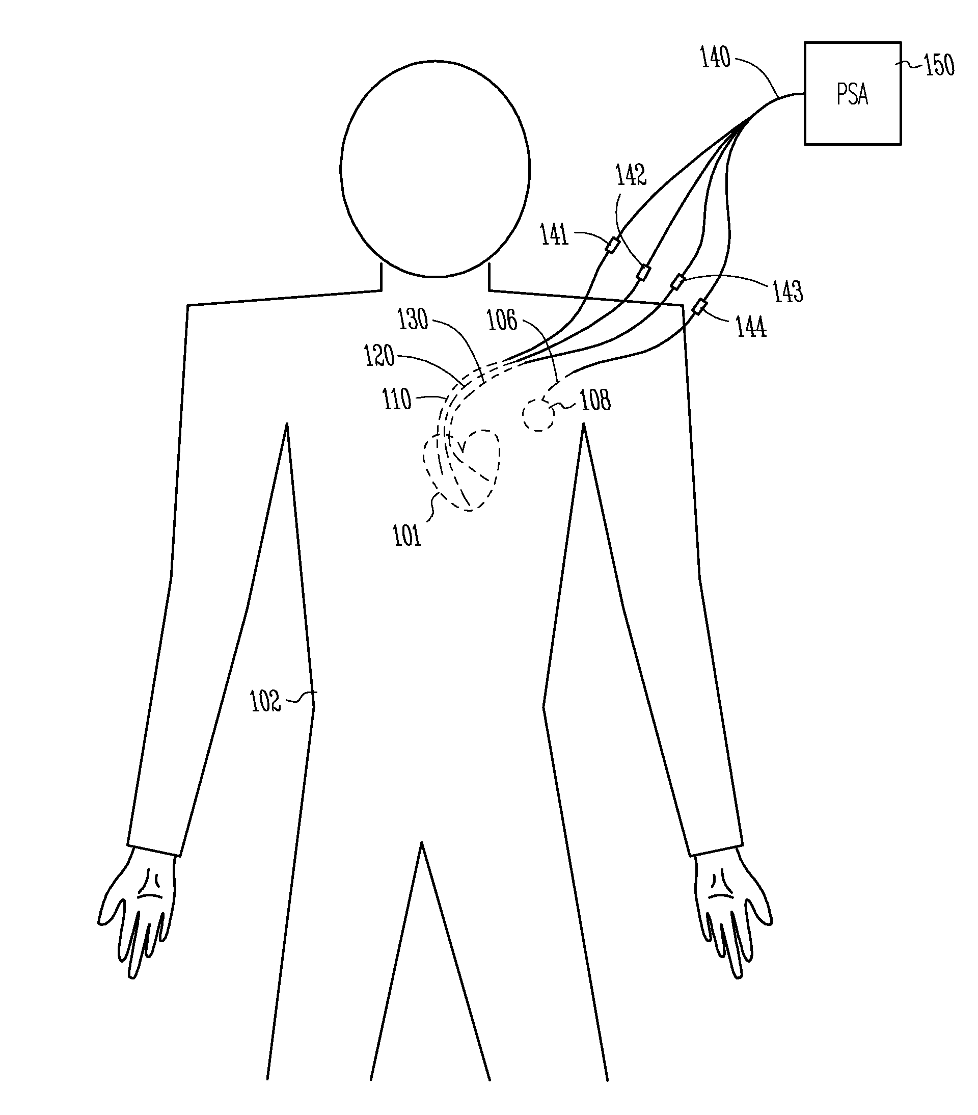
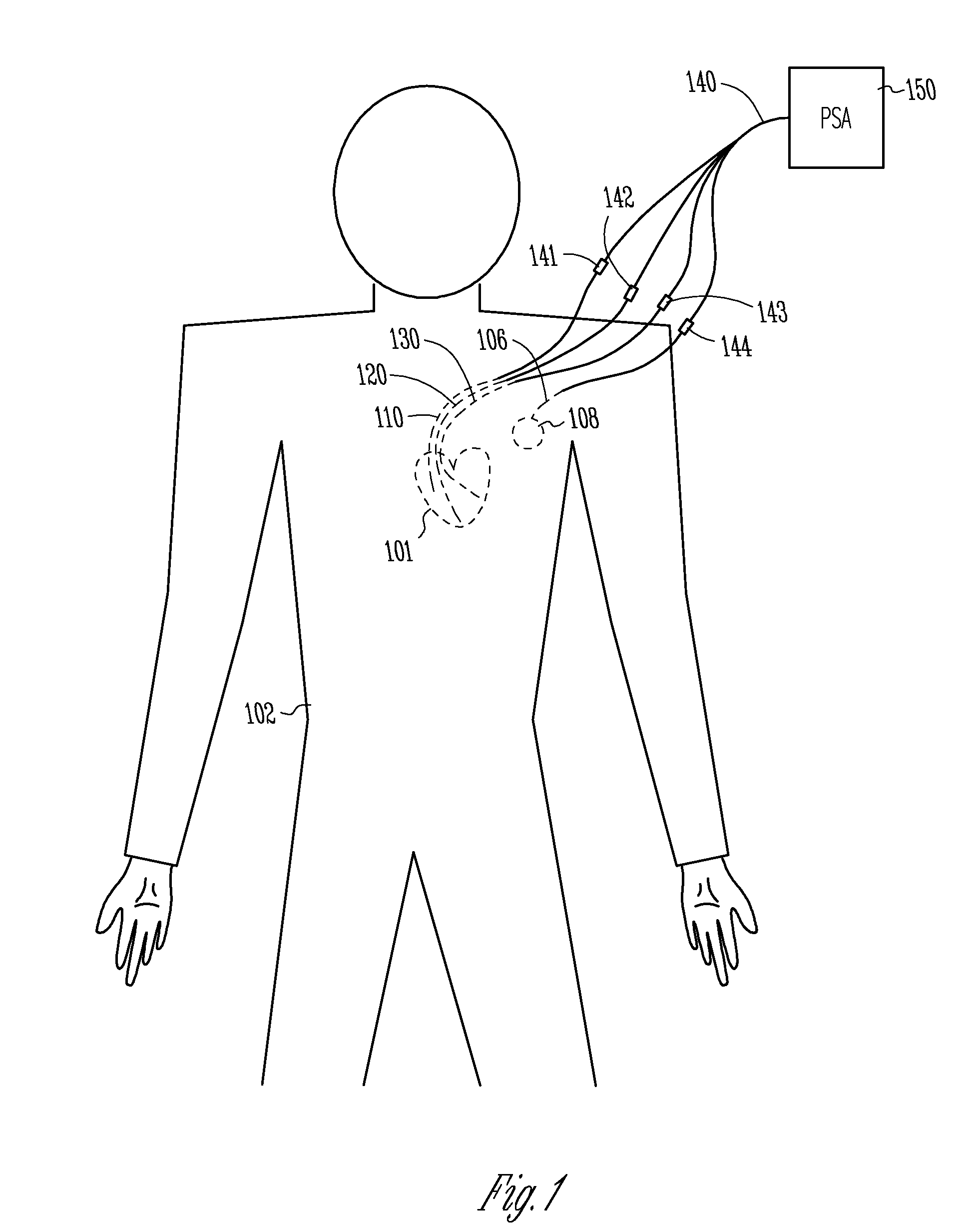
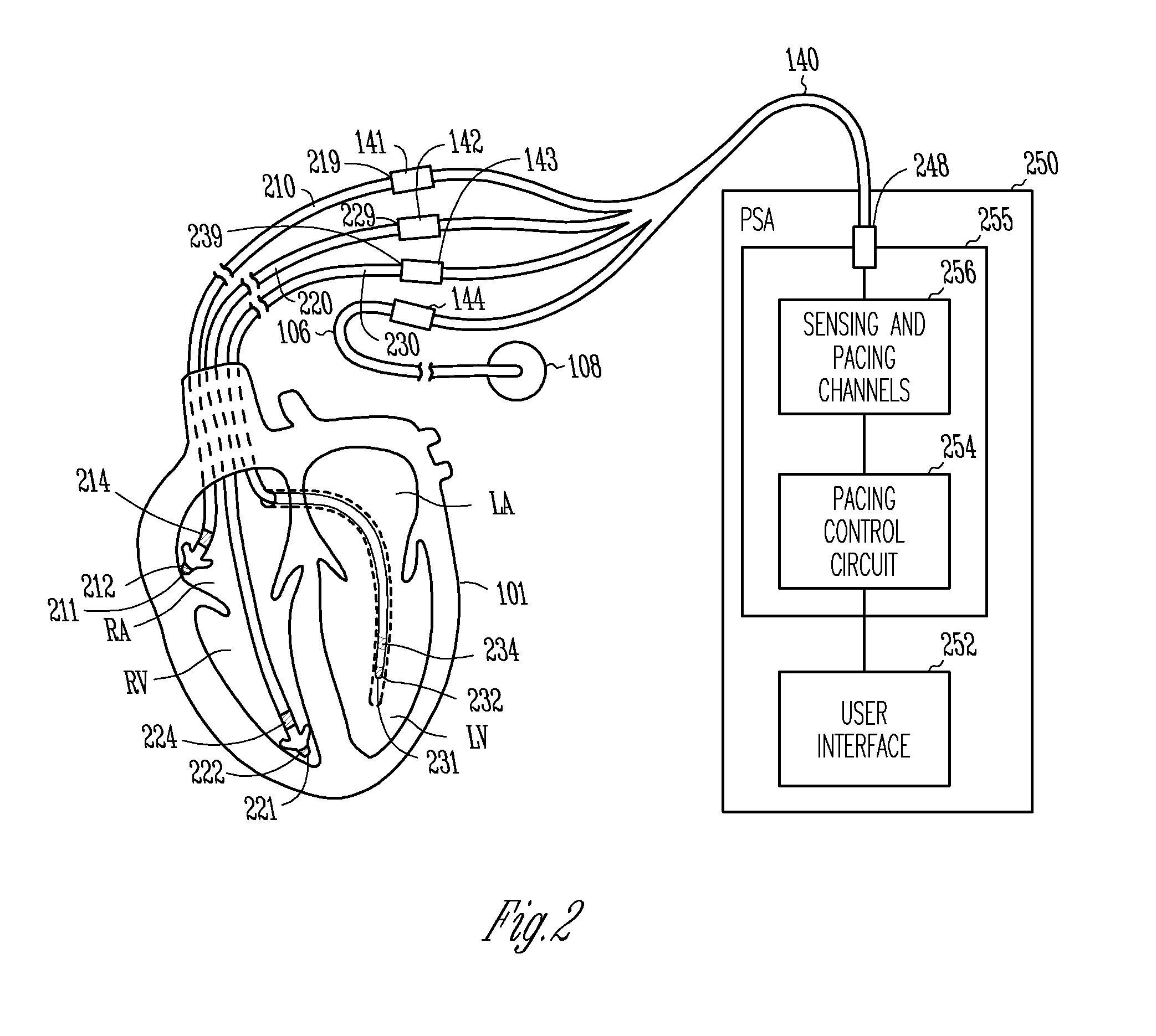
[0024]This document discusses, among other things, a PSA that ...


PUM


Abstract

A pacing system analyzer (PSA) having three or more individually controllable sensing and pacing channels provides for testing and measurement during an operation for implanting a pacemaker having three or more sensing and pacing channels. The PSA allows control and adjustment of pacing parameters including cross-channel pacing parameters relating activities between any two of the three or more channels, such as atrioventricular and interventricular pacing delays. The PSA is also capable of, among other things, displaying real-time cardiac signals, measuring amplitude and slew rate of cardiac depolarizations, and measuring lead impedance for each of the sensing and pacing channels, as well as measuring time intervals between cardiac depolarizations in two different sensing and pacing channels. In one embodiment, the PSA includes individually controllable atrial, right ventricular (RV), and left ventricular (LV) sensing and pacing channels.

Description

CROSS-REFERENCE TO RELATED APPLICATIONS[0001]This application is a Divisional of U.S. application Ser. No. 11 / 124,985, filed May 9, 2005, which is incorporated herein by reference in its entirety.TECHNICAL FIELD[0002]This document generally relates to cardiac rhythm management (CRM) systems and particularly, but not by way of limitation, to a pacing system analyzer (PSA) including three or more independently controlled sensing and pacing channels.BACKGROUND[0003]An implantable pacemaker treats cardiac arrhythmias, heart failure, and / or other cardiovascular disorders by delivering electrical energy to the heart through one or more implantable leads. Before the implantation of the implantable pacemaker, an external (non-implantable) pacing and measuring device known as a pacing system analyzer (PSA) is used to ensure adequate lead placement, maintain basic cardiac functions, and / or evaluate pacing parameters for an initial programming of the implantable pacemaker. In one example of an...

Claims


Application Information

Patent Timeline
Patent Type & Authority Applications(United States)
IPC IPC(8): A61N1/37
CPCA61N1/362G06F19/3406A61N1/372A61N1/37G16H40/63
Inventor DINGMAN, PHILLIPAXELROD, JAY W.MASS, WILLIAM R.KRISHNAN, RADHAKRISHNANKOVTUN, VLADIMIRCHILDS, JEFF
Owner DINGMAN PHILLIP
Why Eureka
Try Eureka