Circular knitting machine for hosiery or the like

Active Publication Date: 2009-12-10
LONATI
View PDF6 Cites 0 Cited by
  • Summary
  • Abstract
  • Description
  • Claims
  • Application Information

AI Technical Summary

Benefits of technology

[0015]The aim of the present invention is to solve the problems described above by providing a circular knitting machine

Problems solved by technology

The presence of these movable cams and of the corresponding actuators, which is necessary in order to produce the various kinds of knitting, has the problem of increasing considerably the complexity of the structure of the entire machine.
Moreover, the presence of these movable cams forces the provision, on board the machine, of an appropriately provided actuation program, which intervenes if an accidental stop of the machine occurs due to failure of the electric power supply and restore

Method used


Image

  • Circular knitting machine for hosiery or the like
  • Circular knitting machine for hosiery or the like
  • Circular knitting machine for hosiery or the like

Examples


first embodiment

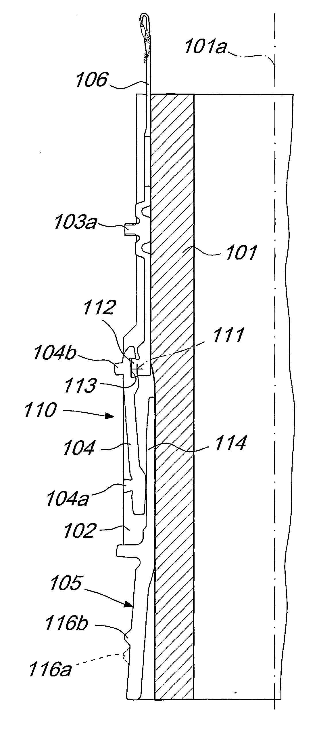
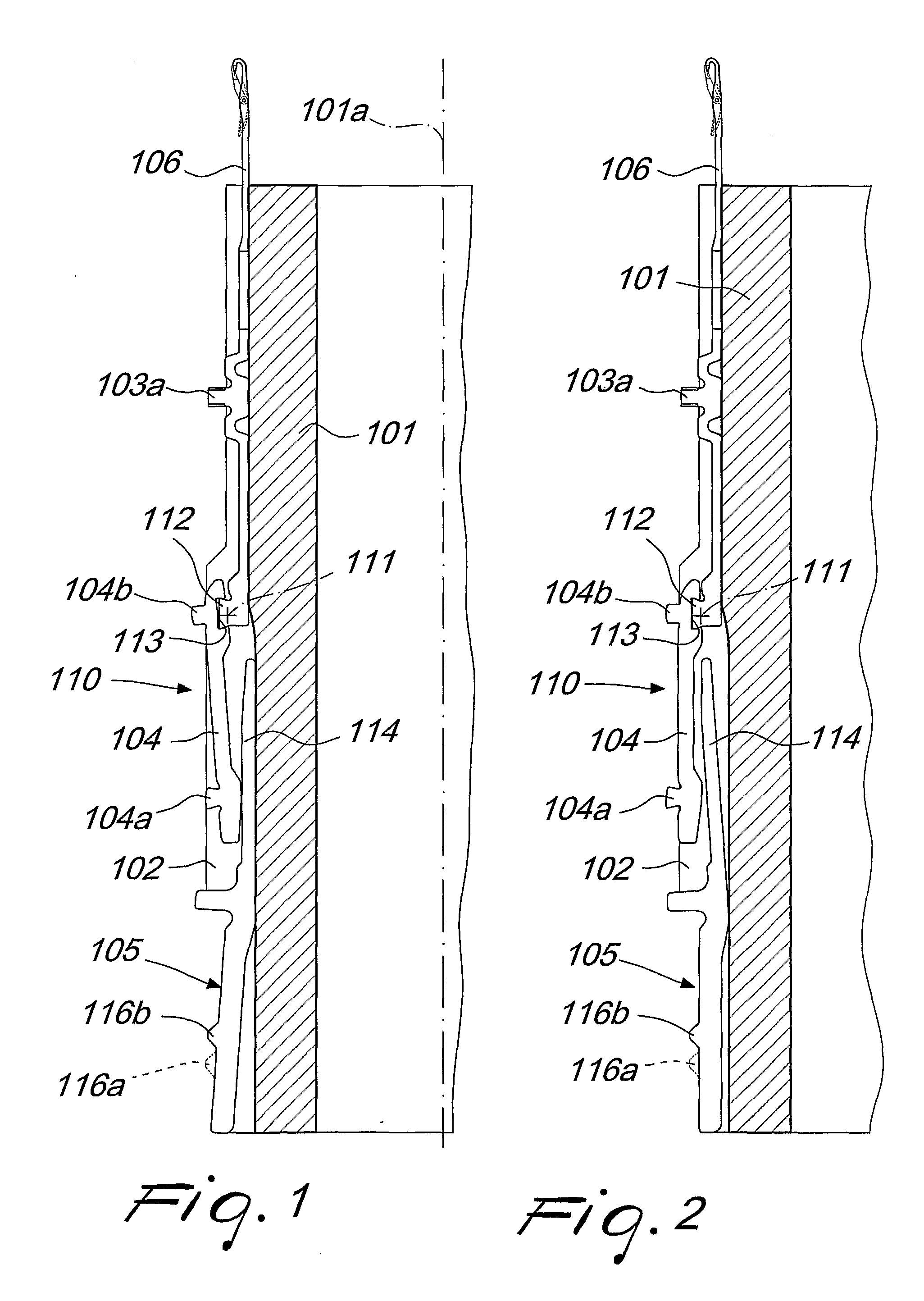
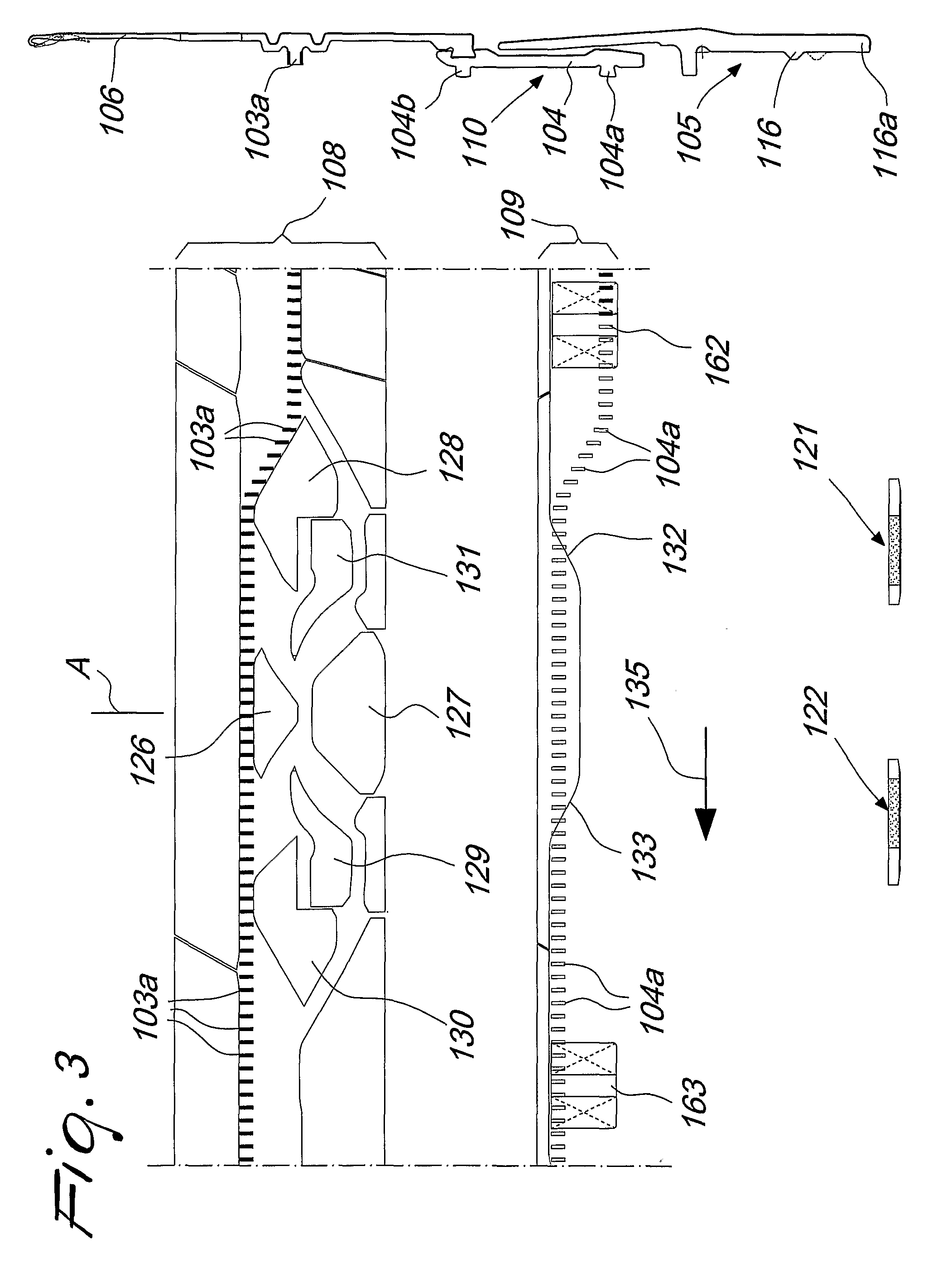
[0032]With reference to the first embodiment shown in FIGS. 1 to 5, which refers to a single-cylinder circular knitting machine for hosiery, the machine according to the invention comprises a needle cylinder 101, which has a vertical axis 101a and has, on its lateral surface, a plurality of axial slots 102, each of which accommodates a needle 106 and an actuation element 110 for the needle 106.

[0033]The actuation element 110 comprises at least one connecting element 104 which is provided, on its side directed toward the outside of the needle cylinder 101, with at least one movable heel 104a. The connecting element 104 can oscillate on a radial plane of the needle cylinder 101 in order to cause the transfer of the movable heel 104a from an active position, shown in FIG. 2, in which the movable heel 104a protrudes radially from the corresponding axial slot 102 of the needle cylinder 101 in order to engage corresponding connecting element actuation cams 109 which face the lateral surfa...

second embodiment

[0050]With reference to the second embodiment shown in FIGS. 6 to 10, which refers to a double-cylinder circular knitting machine for hosiery, the machine according to the invention comprises a lower needle cylinder 1, which has a vertical axis 1a, and an upper needle cylinder 42, which is arranged upward and coaxially with respect to the lower needle cylinder 1. A plurality of mutually aligned axial slots 2, 43 are formed on the lateral surface of the lower needle cylinder 1 and on the lateral surface of the upper needle cylinder 42. An actuation element 10, 10′ for a needle 6 is accommodated in each of the axial slots 2, 43 of the lower needle cylinder 1 and of the upper needle cylinder 42, and a needle 6 with a double head or tip is arranged proximate to the mutually facing axial ends of the needle cylinders 1, 42 in one of the needle cylinders 1, 42.

[0051]The actuation element 10 arranged in the lower needle cylinder 1, referenced hereinafter as “lower actuation element”, compri...


PUM


Abstract

A circular knitting machine for hosiery or the like, which comprises at least one needle cylinder which has a vertical axis and on the lateral surface of which there are axial slots. Each of these axial slots accommodates a needle (106) and an actuation element (110) for the needle (106) which can engage, with one of its ends, the needle (106) arranged in the same axial slot. The needle (106) or the actuation element (110) is provided with a fixed heel (103a), which protrudes radially from the axial slot, and a movable heel (104a) which can be extracted radially on command from the axial slot. Actuation cams are arranged around the needle cylinder and can be engaged by the fixed heels (103a) and by the movable heels (104a) in the extracted position. The machine can perform the usual knitting of known types of machine despite having an actuation cam set which has an extremely small number of actuation cams which can move for activation or deactivation, or none at all.

Description

TECHNICAL FIELD[0001]The present invention relates to a circular knitting machine for hosiery or the like.BACKGROUND ART[0002]As is known, double-cylinder circular knitting machines for hosiery generally comprise a lower needle cylinder which has a vertical axis and an upper needle cylinder which is arranged above and coaxially with respect to the lower needle cylinder, said cylinders being actuatable rigidly with each other with a rotary motion about the common axis.[0003]A plurality of axial slots are formed on the lateral surface of the lower needle cylinder and on the lateral surface of the upper needle cylinder. The axial slots of the upper needle cylinder are aligned with the axial slots of the lower needle cylinder. A selector and a slider are generally accommodated in each of the axial slots of the lower needle cylinder, starting from the bottom, while each of the axial slots of the upper needle cylinder accommodates a slider. Between the two needle cylinders, i.e., in the k...

Claims


Application Information

Patent Timeline
IPC IPC(8): D04B15/34D04B9/00D04B9/46D04B1/16
CPCD04B15/325D04B9/10D04B9/00D04B9/08D04B15/00D04B15/32
Inventor LONATI, ETTORELONATI, TIBERIOLONATI, FAUSTOANDO, JAN
Owner LONATI
Why Eureka
Try Eureka