
Shared tool management system

A tool management and tool technology, applied in the field of shared tool management system, can solve problems such as the inability to count tools

Inactive Publication Date: 2021-05-18
重庆斯铂电气自动化设备有限公司
View PDF1 Cites 0 Cited by
  • Summary
  • Abstract
  • Description
  • Claims
  • Application Information

AI Technical Summary

Problems solved by technology

[0005] The invention provides a shared tool management system, which solves the technical problem that the prior art cannot perform real-time statistics on the number of tools

Method used


Image

  • Shared tool management system
  • Shared tool management system

Examples


Embodiment 1

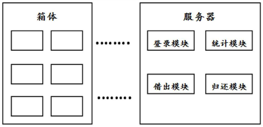
[0034] An embodiment of a shared tool management system of the present invention is basically as attached figure 1 As shown, including: cabinet and server;

[0035] The cabinet has several grids, each grid is equipped with a cabinet door, and the cabinet door is equipped with an induction control door lock; each grid is equipped with an RFID reader, and the RFID reader is installed inside the grid. RFID electronic tags; RFID electronic tags are used to send signals in real time, and RFID readers are used to receive signals in real time and send the identification results to the server;

[0036] The server includes a login module, a statistics module, a lending module and a return module;

[0037] Login module, used for users to log in personal information;

[0038] Statistics module, used for real-time statistics of the number of tools in each cabinet of the cabinet;

[0039] The lending module is used for the user to fill in the name of the tool that the user wants to lend...

Embodiment 2

[0047] The only difference from Embodiment 1 is that the grid includes three specifications of large, medium and small, and in terms of volume, large > medium > small. Through this design, the largest tool is placed in the large grid, the next largest tool is placed in the medium grid, and the smallest tool is placed in the small grid, which is conducive to making full use of the space of the box . In addition, the grids are arranged side by side, and rollers are installed on the bottom of the box, so that the whole box can be moved easily.

Embodiment 3

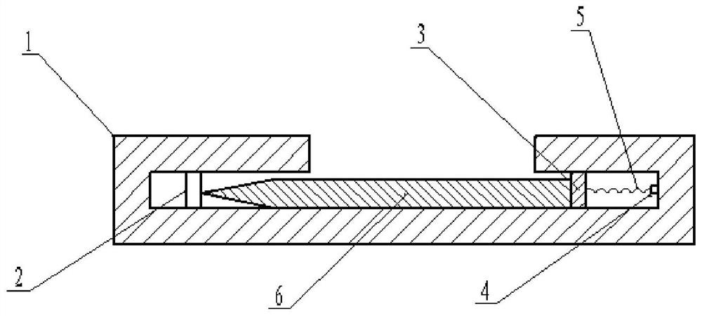
[0049] The only difference with embodiment 2 is that for some special knives 6, for example, the machete of pig bones, this kind of knives are not commonly used in life, so they need to be shared sometimes. When the tool demander returns the special tool 6 , it is necessary to determine whether there is a gap in the special tool 6 .

[0050] Specifically, the box body is provided with a grid for placing special knives 6, as attached figure 2 As shown, it includes: a housing 1, the cross section of the housing 1 is rectangular, and the upper surface of the housing 1 is provided with through holes; a plurality of steel columns 2, the steel columns 2 are located inside the housing 1, and the steel columns 2 are located in the housing 1 on the left side, the upper end of the steel column 2 is welded to the upper surface inside the shell 1, the lower end of the steel column 2 is welded to the lower surface inside the shell 1, and the steel columns 2 are arranged in a straight line...


PUM


Abstract

The invention relates to the technical field of tool management, in particular to a shared tool management system. The system comprises a box body and a server. The box body is provided with a plurality of grids, each grid is provided with a cabinet door, and each cabinet door is provided with an inductive control door lock; each grid is provided with an RFID reader, the RFID readers are installed in the grids, and the tools are provided with RFID electronic tags; the RFID electronic tag is used for sending a signal in real time, and the RFID reader is used for receiving the signal in real time and sending an identification result to the server; the server comprises a login module, a statistics module, a lending module and a returning module; the login module is used for the user to log in personal information; the counting module is used for counting the number of tools in each cabinet of the box body in real time; the lending module is used for lending tools by the user; and the returning module is used for returning the tool by the user. The technical problem that the number of tools cannot be counted in real time in the prior art is solved.

Description

technical field [0001] The invention relates to the technical field of tool management, in particular to a shared tool management system. Background technique [0002] For scattered tools, they are small in size, large in number, not fixed in location, and can be used at random. Most of them are managed by manual distribution and input. On the one hand, it is time-consuming and labor-intensive. Or the entered information does not match the actual tool. [0003] In this regard, document CN108710997A discloses a hand tool management method, including: obtaining the user's RFID identity information through an RFID identifier; when the RFID identity information matches the pre-stored RFID identity information, controlling the hand tool management drawer The tool management lock is opened so that the user can pick and place the hand tool; receive the hand tool pick and place information generated by the user through the hand tool pick and place operation; collect the RFID identi...

Claims


Application Information

Patent Timeline
IPC IPC(8): G06K17/00B25H3/02B25H5/00
CPCB25H3/02B25H5/00G06K17/0029
Inventor 牟治宇
Owner 重庆斯铂电气自动化设备有限公司
Learn More