Post-wall waveguide based short slot directional coupler, butler matrix using the same and automotive radar antenna

a short slot directional coupler and waveguide technology, applied in the direction of waveguides, slot antennas, antennas, etc., can solve the problems of multi-step models, difficult fabrication, and difficult fabrication in microwave band and millimeter wave band

Active Publication Date: 2009-12-10
KK TOSHIBA
View PDF0 Cites 29 Cited by
  • Summary
  • Abstract
  • Description
  • Claims
  • Application Information

AI Technical Summary

Benefits of technology

[0021]FIG. 11 is a perspective view of a short slot directional coupler according to a fourth embodiment.
[

Problems solved by technology

A multi-stepped model short slot directional coupler using the waveguide disclosed in Akihiro Hino, et al. is difficult to fabrication, because the waveguid

Method used


Image

  • Post-wall waveguide based short slot directional coupler, butler matrix using the same and automotive radar antenna
  • Post-wall waveguide based short slot directional coupler, butler matrix using the same and automotive radar antenna
  • Post-wall waveguide based short slot directional coupler, butler matrix using the same and automotive radar antenna

Examples


first embodiment

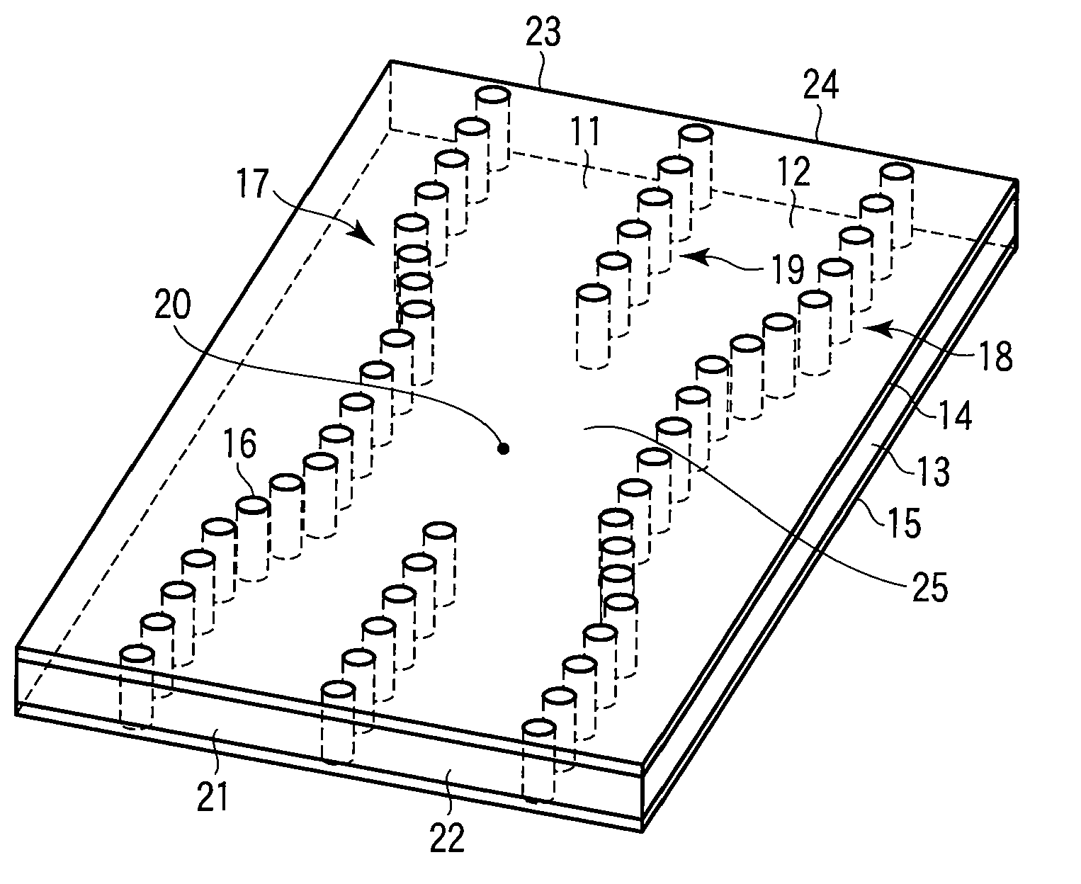
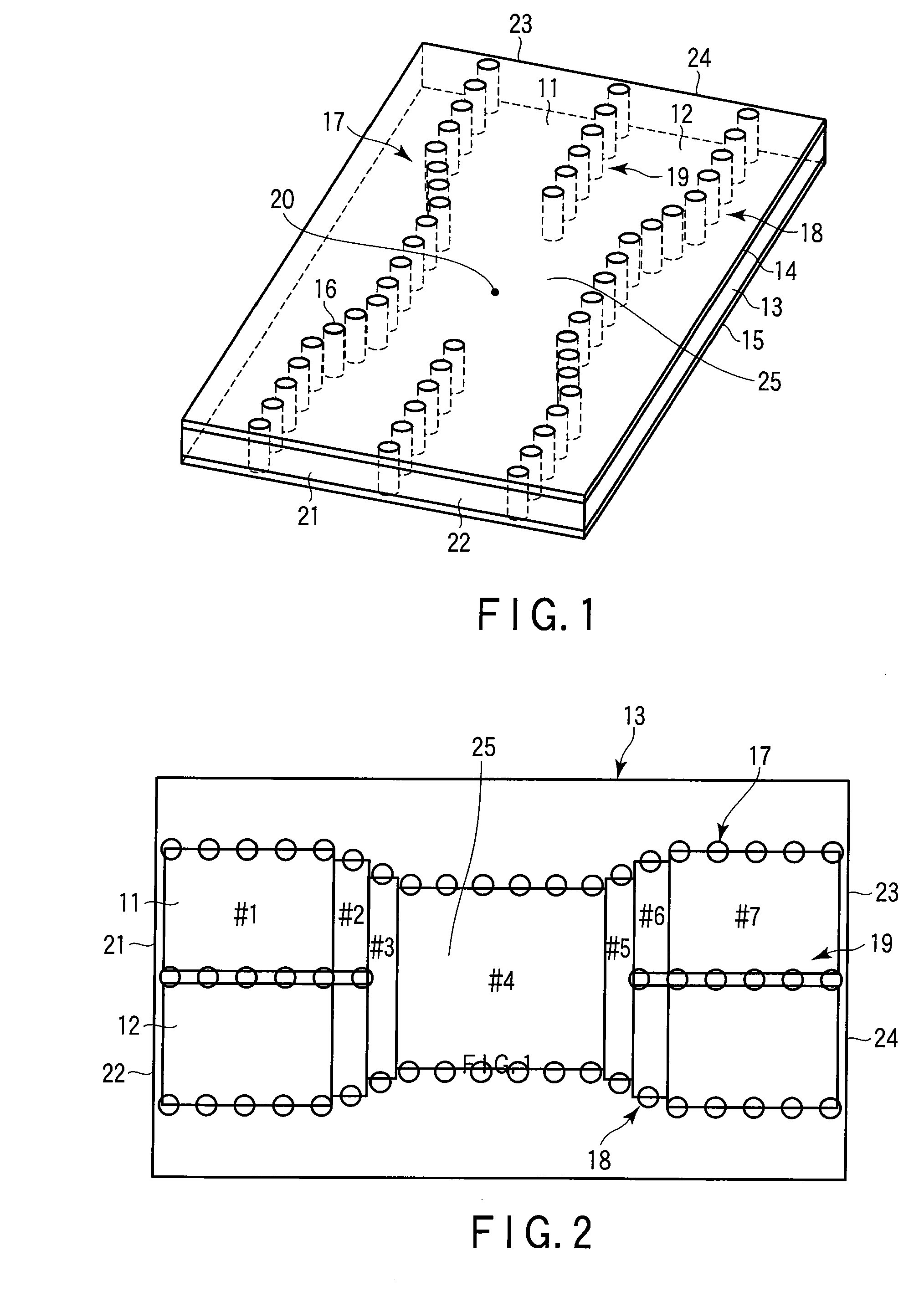
[0024]The short slot directional coupler according to the first embodiment will be explained in conjunction with FIGS. 1 and 2. This short slot directional coupler is realized by use of two post-wall waveguides 11 and 12. The post-wall waveguides 11 and 12 are comprised of a dielectric substrate 13 and via-holes 16 penetrating through the dielectric substrate 13. The upper and lower surfaces of the dielectric substrate 13 are covered by the metal films 14 and 15 made of electric conductor material such as copper. Each via-hole 16 is made of a metal component (referred to as a via-hole component) penetrating through the dielectric substrate 13 and short-circuits the metal films 14 and 15.

[0025]First, second and third via-hole strings 17, 18 and 19 each are formed of via-holes 16, and comprise first, second and third post wall waveguides 11, 12 and 25. The first post-wall waveguide 11 is comprised of the first via-hole string 17 and the third via-hole string 19. The second post-wall w...

second embodiment

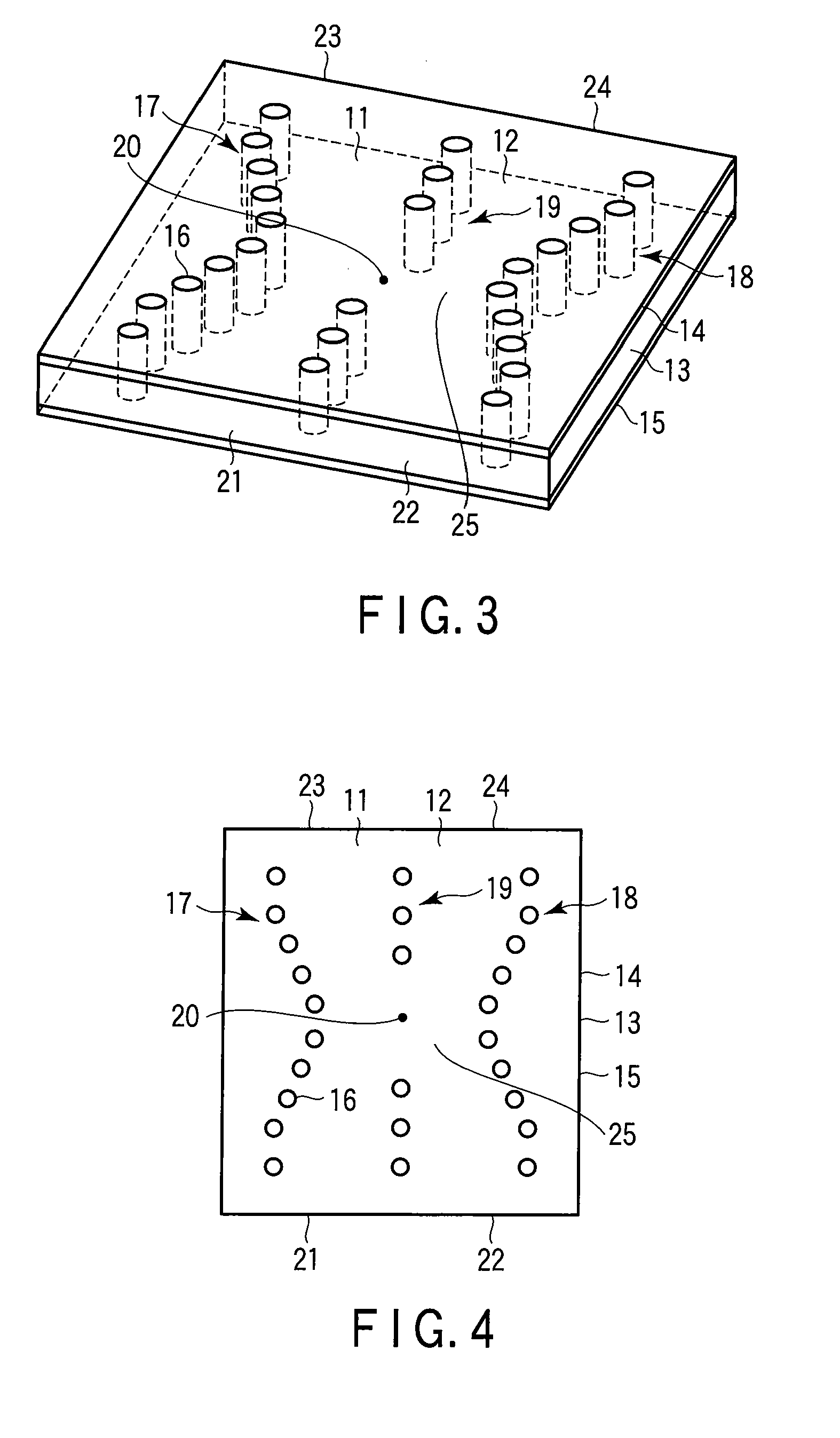
[0047]An example applying the short slot directional coupler according to the first embodiment to a Butler matrix will be described hereinafter. As shown in FIG. 9, the Butler matrix comprises 3 dB hybrid couplers 31A to 31D shown in FIGS. 3 and 4, 0 dB cross couplers 32A and 32B shown in FIGS. 5 and 6, and phase shifters 33A to 33D having a phase shifter. The phase shifters 33A to 33D each are comprised of the post-wall waveguide similarly to the coupler.

[0048]An example of a 4-way Butler matrix is shown in FIG. 9. Even if a power inputs to any one of input ports P1 to P4, the power is distributed equally from output ports P5 to P8. The input ports P1 and P2 are the first and second I / O ports of the hybrid coupler 31A, and the input ports P3 and P4 are the first and second I / O ports of the hybrid coupler 31B.

[0049]The third I / O port which is the output port of the hybrid coupler 31A is connected to the input port of the phase shifter 33A, and the fourth I / O port which is another ou...

third embodiment

[0053]FIG. 10 shows an automotive radar antenna according to the third embodiment of the present invention. The radar antenna has a two-layer structure wherein a slot array antenna 42 having a plurality of slots 43 is arranged on the Butler matrix 41 using the short slot directional coupler comprised of the post-wall waveguide as shown in FIG. 9. In this case, the Butler matrix 41 is used as a power supply circuit for the slot array antenna 42.


PUM


Abstract

A short slot directional coupler includes a dielectric substrate having both surfaces each covered by a metal film, a first via-hole string and a second via-hole string, each of which has via-holes penetrating through the substrate, and formed so that a distance between the first via-hole string and the second via-hole string is narrow at a center of a length direction of the string and wider along directions of both ends of the string, and a pair of third via-hole strings each having via-holes penetrating through the substrate, and formed between parts adjacent to both ends of the first via-hole string and parts adjacent to both ends of the second via-hole string to form a first post-wall waveguide along with the first via-hole string and a second post-wall waveguide along with the second via-hole string.

Description

CROSS-REFERENCE TO RELATED APPLICATIONS[0001]This application is based upon and claims the benefit of priority from prior Japanese Patent Application No. 2008-148436, filed Jun. 5, 2008, the entire contents of which are incorporated herein by reference.BACKGROUND OF THE INVENTION[0002]1. Field of the Invention[0003]The invention relates to a post-wall waveguide based short slot directional coupler, a Butler matrix using the same, and an automotive radar antenna.[0004]2. Description of the Related Art[0005]In general, a short slot directional coupler comprises waveguides which differ in width from each other and connected in a multi-stepped form. For example, Akihiro Hino, Tadashi Kawai, Yoshihiro Kokubo, and Isao Ohta “A Design of Broad-Band Copact H-Plane Directional Coupler” Department of Electronics, faculty of engineering, Himeji Institute of Technology, MW2000-163, (2000-12) (referred to as Akihiro Hino et al. hereinafter) discloses a short slot directional coupler having a cou...

Claims


Application Information

Patent Timeline
IPC IPC(8): H01Q1/50H01P5/18H01P5/12H01Q13/10
CPCH01P5/182H01P3/121
Inventor SHIJO, TETSUOBAYASHI, SHUICHI
Owner KK TOSHIBA
Why Eureka
Try Eureka