Filter

A filter and waveguide technology, applied in waveguide-type devices, waveguides, resonators, etc., can solve problems such as the center frequency shift of the passband

Inactive Publication Date: 2021-09-10
THE FUJIKURA CABLE WORKS LTD
View PDF4 Cites 0 Cited by
  • Summary
  • Abstract
  • Description
  • Claims
  • Application Information

AI Technical Summary

Problems solved by technology

[0008] On the other hand, in the BPF using the cylindrical wall waveguide, there is a problem that the center frequency of the passband tends to shift according to the ambient temperature.

Method used


Image

  • Filter
  • Filter
  • Filter

Examples


Embodiment Construction

[0021] [Structure of bandpass filter]

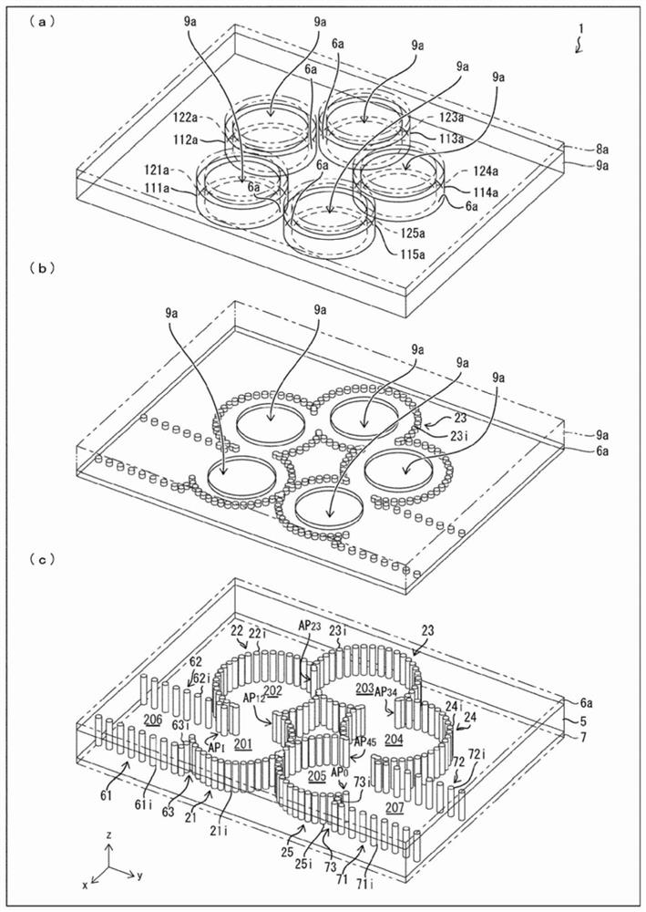
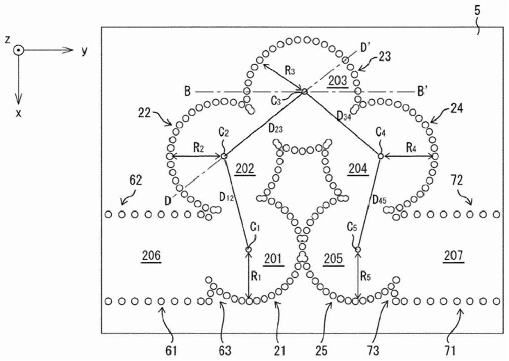
[0022] refer to figure 1 , image 3 , Figure 4 of (a), Figure 5 (a) and Figure 6 , the bandpass filter 1 (hereinafter also simply referred to as "BPF1") according to the first embodiment of the present invention will be described. figure 1 It is an exploded perspective view of BPF 1 according to this embodiment. image 3 yes figure 1 The top view of the exploded perspective view shown in (c). Figure 4 (a) is figure 1 The top view of the exploded perspective view shown in (a). Figure 5 (a) is figure 1 The top view of the exploded perspective view shown in (b). Figure 6 yes image 3 The cross-sectional view of BPF1 at the cutting line B-B' of .

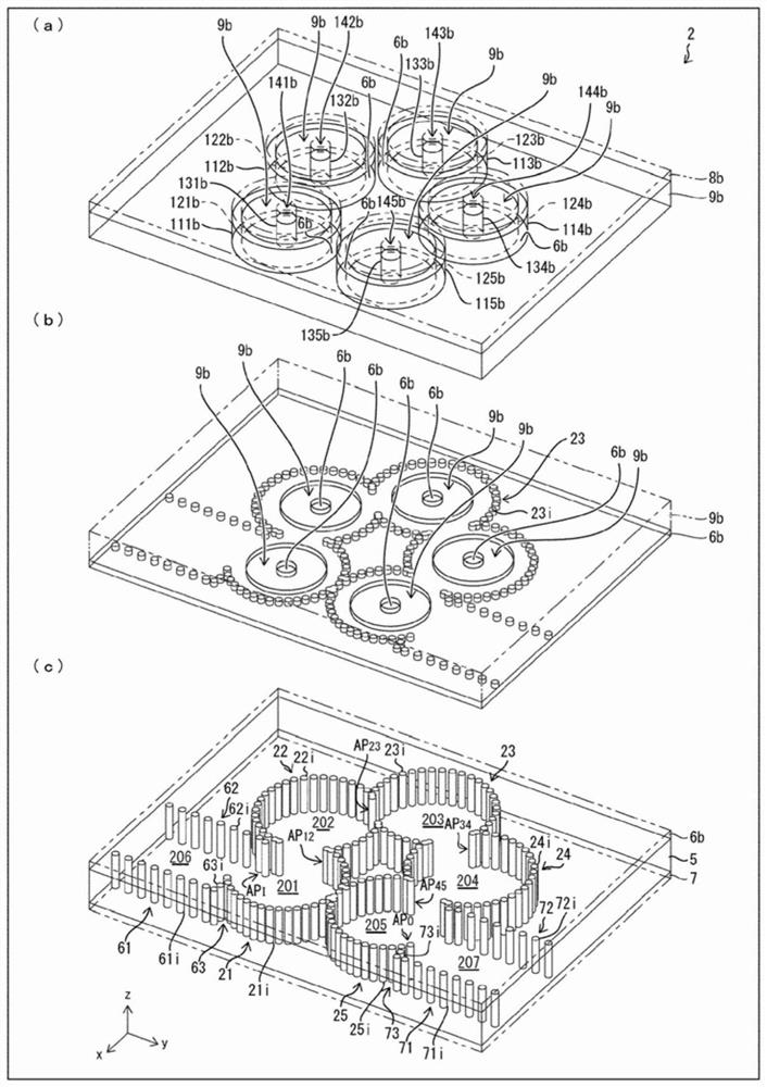
[0023] refer to figure 2 , image 3 , Figure 4 of (b), Figure 5 (b) and Figure 7 , the bandpass filter 2 (hereinafter also simply referred to as "BPF2") according to the second embodiment of the present invention will be described. figure 2 It is an exploded perspectiv...


PUM


Abstract

The present invention realizes a filter that can compensate for characteristics changes accompanying temperature change. This filter (1) comprises: a post wall waveguide that functions as resonators (201-205) that are coupled electromagnetically; and cavities (301a-305a) that are coupled electromagnetically with the resonators (201-205) with coupling windows (AP101a-AP105a) formed on a second conductor layer (6a) of the post wall waveguide interposed therebetween. A substrate (5) of the post wall waveguide includes a first dielectric layer comprising a first dielectric, and provided inside each cavity (301a-305a) is a second dielectric layer (9a) comprising a second dielectric. In the filter (1), the dielectric constant of the first dielectric increases in conjunction with temperature rise, and the dielectric constant of the second dielectric decreases in conjunction with temperature rise in the same range as the abovementioned temperature rise, or alternatively, the dielectric constant of the first dielectric decreases in conjunction with temperature rise, and the dielectric constant of the second dielectric increases in conjunction with temperature rise in the same range as the abovementioned temperature rise.

Description

technical field [0001] The present invention relates to a filter using a cylindrical wall waveguide. In particular, it concerns filters with temperature compensation. Background technique [0002] It is known that a plurality of resonators with electromagnetic coupling function as a bandpass filter (Bandpass Filter. Hereinafter, also described as “BPF”) that selectively passes electromagnetic waves in a specific frequency band (hereinafter also described as “pass band”). Features. [0003] Non-Patent Document 1 discloses a bandpass filter using a metal waveguide that functions as a plurality of resonators. In addition, in Non-Patent Document 1, a technique for adjusting the center frequency in this bandpass filter is disclosed. [0004] Non-Patent Document 2 discloses a bandpass filter using a cylindrical waveguide functioning as a plurality of resonators. Here, the pillar wall waveguide refers to a conductor pillar in which wide walls are provided on both main surfaces ...

Claims


Application Information

Patent Timeline
Patent Type & Authority Applications(China)
IPC IPC(8): H01P1/208H01P7/06H01P3/12
CPCH01P1/2088H01P1/208H01P3/12H01P7/06
Inventor 上道雄介
Owner THE FUJIKURA CABLE WORKS LTD
Why Eureka
Try Eureka