Internal antennas for mobile communication devices

a mobile communication device and antenna technology, applied in the direction of antennas, slot antennas, antenna details, etc., can solve the problems of reducing the efficiency of small antennas, requiring higher power supply, and impracticality of dimensions, and achieve good results

Inactive Publication Date: 2002-10-15
IN4TEL
View PDF14 Cites 135 Cited by
  • Summary
  • Abstract
  • Description
  • Claims
  • Application Information

AI Technical Summary

Benefits of technology

Thus, curving the slot while yet exciting it by a distributed feed line having a feed end (preferably including a transformer effected by changing its length and width in order to match the slot impedance) and a load end (which includes a reactive load--either an open stub, short stub or lumped elements for mainly reducing the reactive part of the slot impedance to a level of zero) provides particularly good results when curving the slot, and exciting it by a distributed feed line.
A multi slot configuration can be made according to the present invention, by having two slots excited either serially by the same feed line, e.g., crossing the first slot at its excitation point, continuing to second slot, crossing the second slot at its excitation point, and then having the load end part of the feed line. This embodiment enables the entire antenna to operate at the further frequency bands.

Problems solved by technology

For advanced mobile communication devices, e.g., cellular handset units, such dimension are impractical since the overall handset dimension is smaller than half a wavelength of the appropriate frequency.
Using small antennas reduces their efficiency, and hence requires higher power to be supplied in order to operate the device.
Higher power causes shorter battery cycles between charging and increases the radiation into the user's head / body.
The level of power radiated into the human head is most significant, and serious limitations and specifications are prescribed in order to protect the users.
The result is a requirement for higher power to operate the device with the consequent disadvantages described above.
The use of external whip antennas, such the "STUBBY" or retractable antennas, is also inconvenient, as the antennas are often "caught up" inside the pocket.
They also detract from the aesthetic appearance of the mobile communication device and most important--the radiation pattern is quasi-omni, so no enhancement is achieved in radiation at the user's head / body.
Internal antennas supplied by several companies are relatively inefficient as compared to external antennas.
The antenna gain is also generally poor (especially while used adjacent to the head / body), and the SAR (Specific Absorption Ratio) results are generally high.
Another problem in the known internal antenna is the narrow bandwidth of operation.
The latter is considered an even more difficult problem in cases where dual frequency bands or triple-band operations of the mobile communication devices are required, such as cellular GSM 900 / 1800, 900 / 1900, 900 / 1800 / 1900 MHz, etc.
Unfortunately, such elements, because of the small size of the mobile communication device, will show very low efficiency and hence low gain, and it will be difficult to match their impedance to that of the mobile communication device.
As a result, this configuration is more complex to match by means of the relative part of the slot impedance.
Furthermore, a floating ground would decrease the antennas efficiency.
There are a number of disadvantages of such configuration as suggested by this patent.
Thus, the matching of such a slot is very difficult due to the centered excitation point (as described above and in U.S. Pat. No. 5,068,670).
Further, the excitation is complex and costly to implement.
Finally, slots which are open-ended at one end are less efficient as compared to short-ended slots, and cause radiation in undesired directions.
There are a number of disadvantages of such configuration as suggested by this patent.
The slot is excited at its center point, and is very small as compared to the wavelength at the operational frequency; hence it does not radiate efficiently.
It is complicated to build and relatively expensive, and no real reduction in the radiation at the user's head / body is achieved.
For modern mobile communication devices, which are very compact in size, such dimensions are impractical.

Method used


Image

  • Internal antennas for mobile communication devices
  • Internal antennas for mobile communication devices
  • Internal antennas for mobile communication devices

Examples


Embodiment Construction

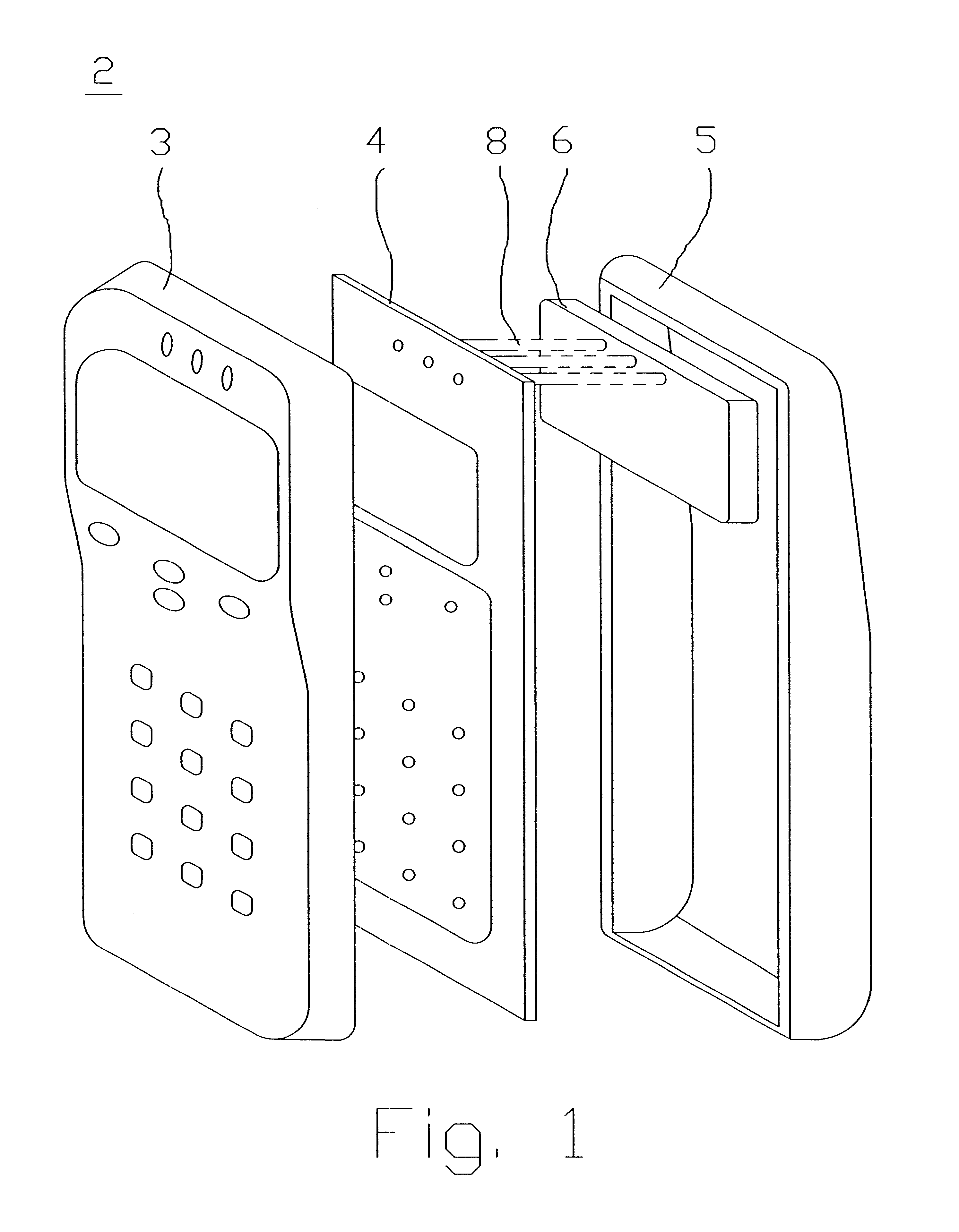
FIG. 1 illustrates the main components of a mobile communication device, such as a cellular telephone handset, constructed in accordance with the present invention. Such a device, generally designated 2, includes a front cover 3, a main PCB (printed circuit board) 4, and a back cover 5 usually also containing the battery (not shown). The foregoing components may be conventional, and therefore further details are not set forth.

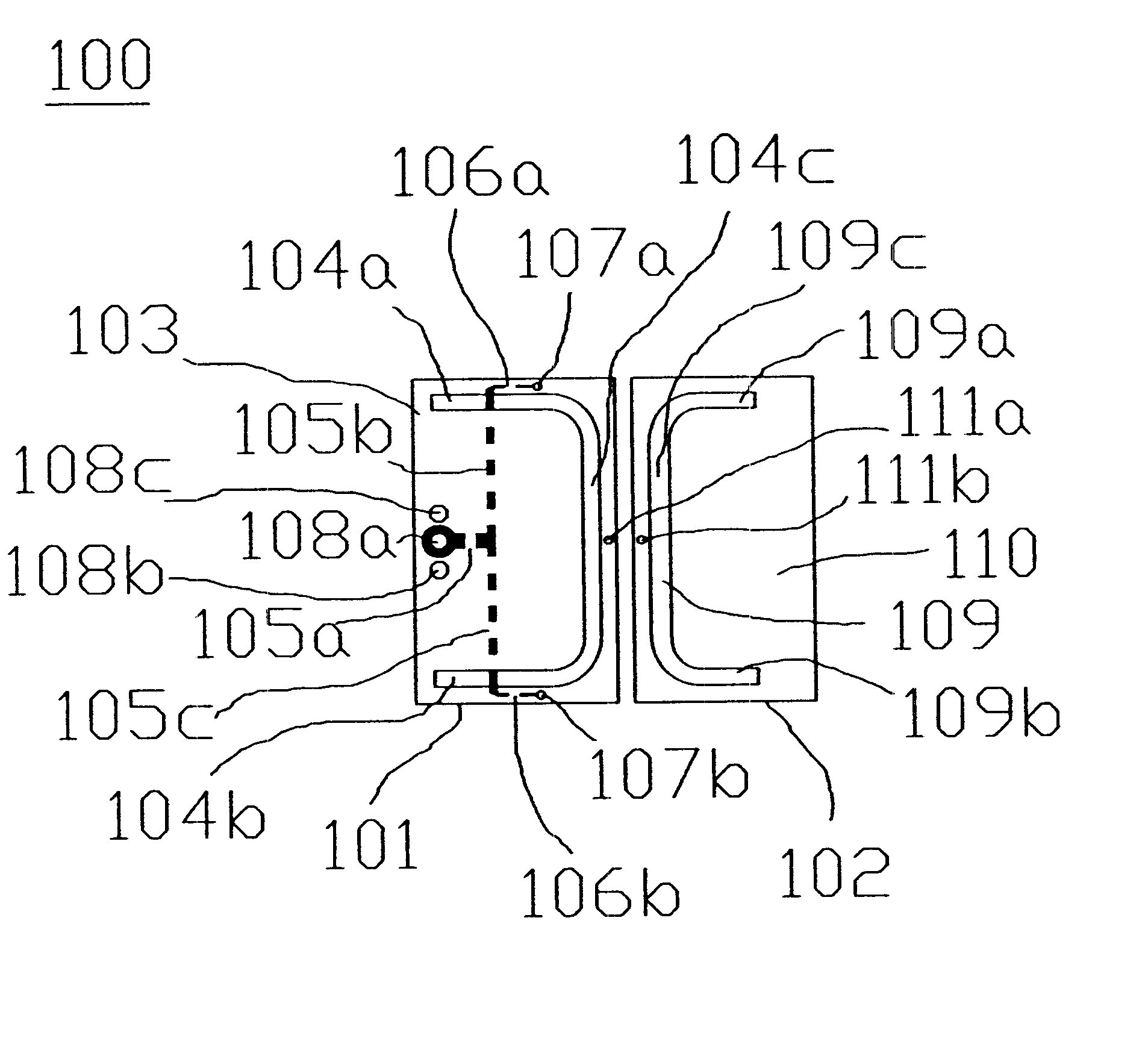
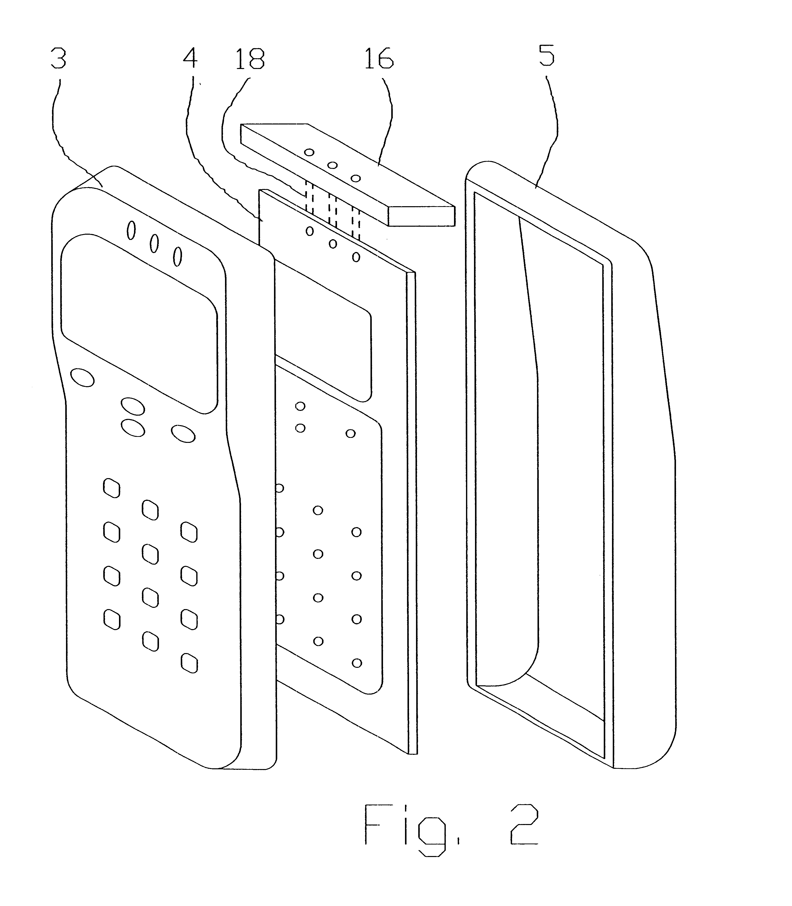
In accordance with the present invention, the mobile device 2 includes an internal antenna, generally designated 6, disposed between the main PCB 4 and the back cover 5 and connected to the PCB by feeding pins 8. In the embodiment illustrated in FIG. 1, the internal antenna 6 is located substantially parallel to the plane of the main PCB 4 to which it is connected by the feeding pins 8. FIG. 2 illustrates a variation wherein the internal antenna, therein designated 16, is disposed substantially perpendicular to the main PCB 4 to which it is connected by feeding...


PUM


Abstract

A multi-band microwave antenna which is resonant and radiant at a high frequency band and at one or more lower frequency bands includes an electrically-conductive ground plane on one face of a dielectric substrate; an electrically conductive strip line on the opposite face of the dielectric substrate; a curved slot formed in the ground plane having a feed side electromagnetically coupled to the feed end of the strip line, and a load side electromagnetically coupled to the load end of the strip line, such that the slot is resonant and radiant at the high frequency band; and a further electrical conductor electrically connected to the ground plane to serve as a continuation thereof at the load side of the slot and electromagnetically coupled to the slot at the lower frequency bands such as to cause the slot to be resonant and radiant also at the lower frequency band or bands.

Description

The present invention relates generally to antennas and, more particularly, to small and high efficiency antennas for mobile and handset communication devices.Mobile communication devices are becoming smaller as the technology is developed. For an antenna to operate properly, it should usually be about half a wavelength in size, except for monopole-like antennas (which normally operate above a ground plane), where a quarter wavelength is required. For advanced mobile communication devices, e.g., cellular handset units, such dimension are impractical since the overall handset dimension is smaller than half a wavelength of the appropriate frequency.Using small antennas reduces their efficiency, and hence requires higher power to be supplied in order to operate the device. Higher power causes shorter battery cycles between charging and increases the radiation into the user's head / body. The level of power radiated into the human head is most significant, and serious limitations and spec...

Claims


Application Information

Patent Timeline
Patent Type & Authority Patents(United States)
IPC IPC(8): H01Q1/24H01Q13/10H01Q13/16H01Q5/00H01Q1/38H01Q21/30H01Q5/10H01Q5/378H01Q5/40
CPCH01Q1/243H01Q1/38H01Q5/40H01Q21/30H01Q5/378H01Q13/16H01Q13/10
Inventor MAOZ, JOSEPHKADICHEVITZ, MICHAEL
Owner IN4TEL
Why Eureka
Try Eureka