Power transmission control device, power transmission device, power reception control device, power reception device, electronic apparatus, and contactless power transmission system

a technology of power transmission control and control device, which is applied in the direction of battery data exchange, inductance, transportation and packaging, etc., can solve the problems of reducing the efficiency of the power transmission driver, increasing the on-loss of the switching element with respect to the entire electrical power, and generating on-loss of the switching element. , to achieve the effect of reducing transmission power, reducing transmission power, and achieving desirable power saving in the system

Active Publication Date: 2010-09-09
SAMSUNG ELECTRONICS CO LTD
View PDF4 Cites 123 Cited by
  • Summary
  • Abstract
  • Description
  • Claims
  • Application Information

AI Technical Summary

Benefits of technology

[0012]In accordance with some embodiments of the invention, transmission power can be freely adjusted while maintaining the efficiency of a power transmission driver high, and desirable power saving in a system can be realized by sufficiently reducing the transmission power, for example, in a period where the level of the transmission power can be low. Moreover, it is also possible to provide a transmission power varying technology of high practical value that can be used in, for example, a novel foreign object detection system.

Problems solved by technology

When a contactless power transmission system is to be put in practical use, a reduction of power consumption of the contactless power transmission system is an important issue.
Further, as parasitic diodes (body diodes) are present between sources and drains of the MOS transistors, on-loss would also be generated in the parasitic diodes (body diodes) through which regeneration current flows.
However, as the power supply voltage of the power transmission driver lowers, the proportion of the on-loss of the switching elements with respect to the entire electrical power increases, and the on-loss becomes more prominent, which leads to a problem in that the efficiency of the power transmission driver (i.e., the conversion efficiency of the DC / AC converter circuit) is lowered.
However, with a reduction in the power supply voltage (operation voltage), on-loss relating to each of the switching elements forming the power transmission driver becomes more prominent, and therefore it is in effect difficult to lower the power supply voltage (operation voltage) of the power transmission driver to a desired voltage level, which poses a limitation to the reduction (control) of transmission power.
When the operation of signal transmission to the power transmission device is stopped, a time-out error occurs at the time of reception processing on the primary side, such that the power transmission device automatically goes into a standby state.

Method used


Image

  • Power transmission control device, power transmission device, power reception control device, power reception device, electronic apparatus, and contactless power transmission system
  • Power transmission control device, power transmission device, power reception control device, power reception device, electronic apparatus, and contactless power transmission system
  • Power transmission control device, power transmission device, power reception control device, power reception device, electronic apparatus, and contactless power transmission system

Examples


first embodiment

[0061]Preferred embodiments of the invention are described in detail below. It is noted that the embodiments described below should not unduly limit the content of the invention recited in the scope of the claimed invention, and all of the compositions to be described in the embodiments may not necessarily be indispensable as means for solution provided by the invention.

[0062]Exemplary Composition of Power Transmission Device

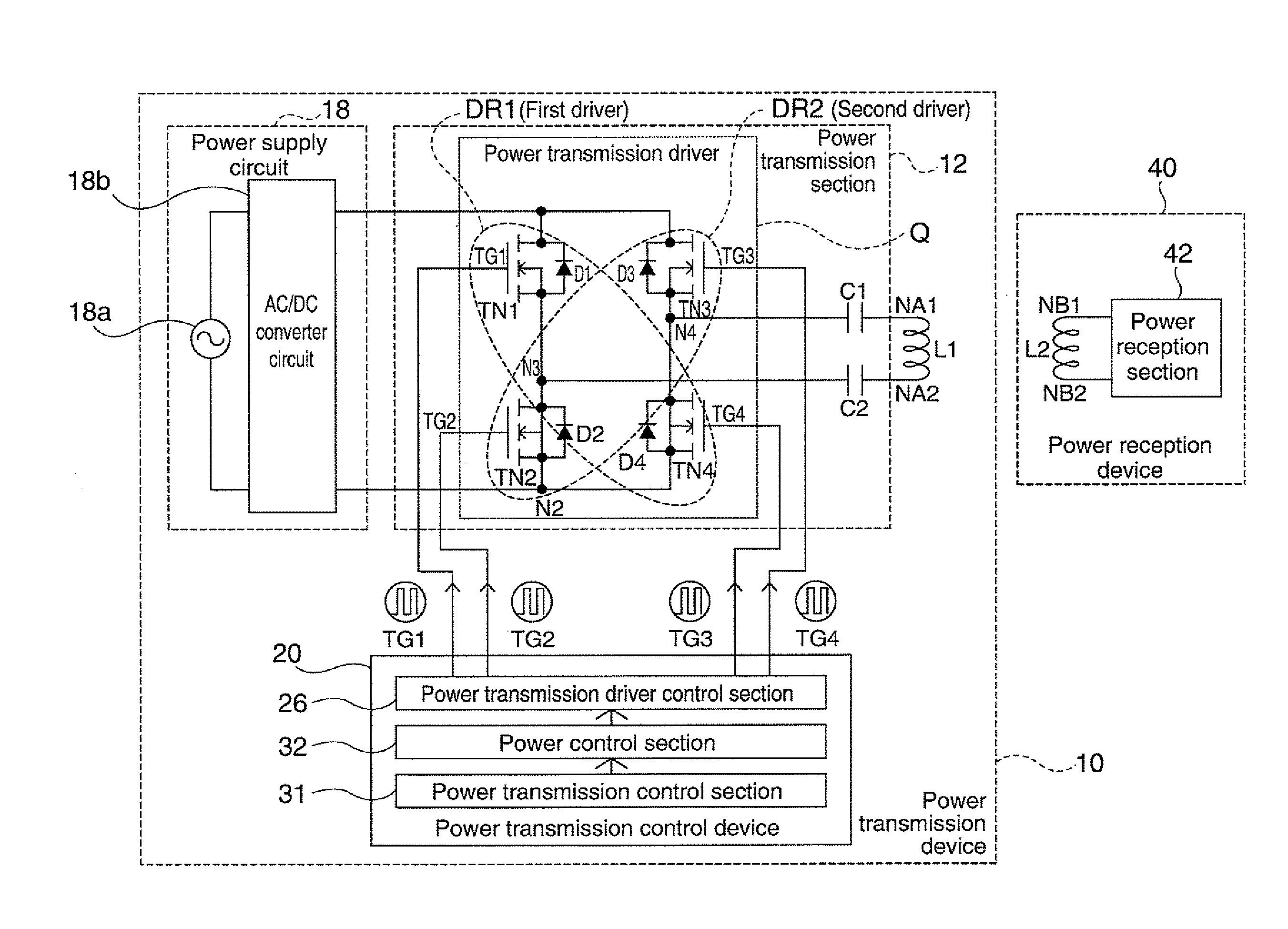
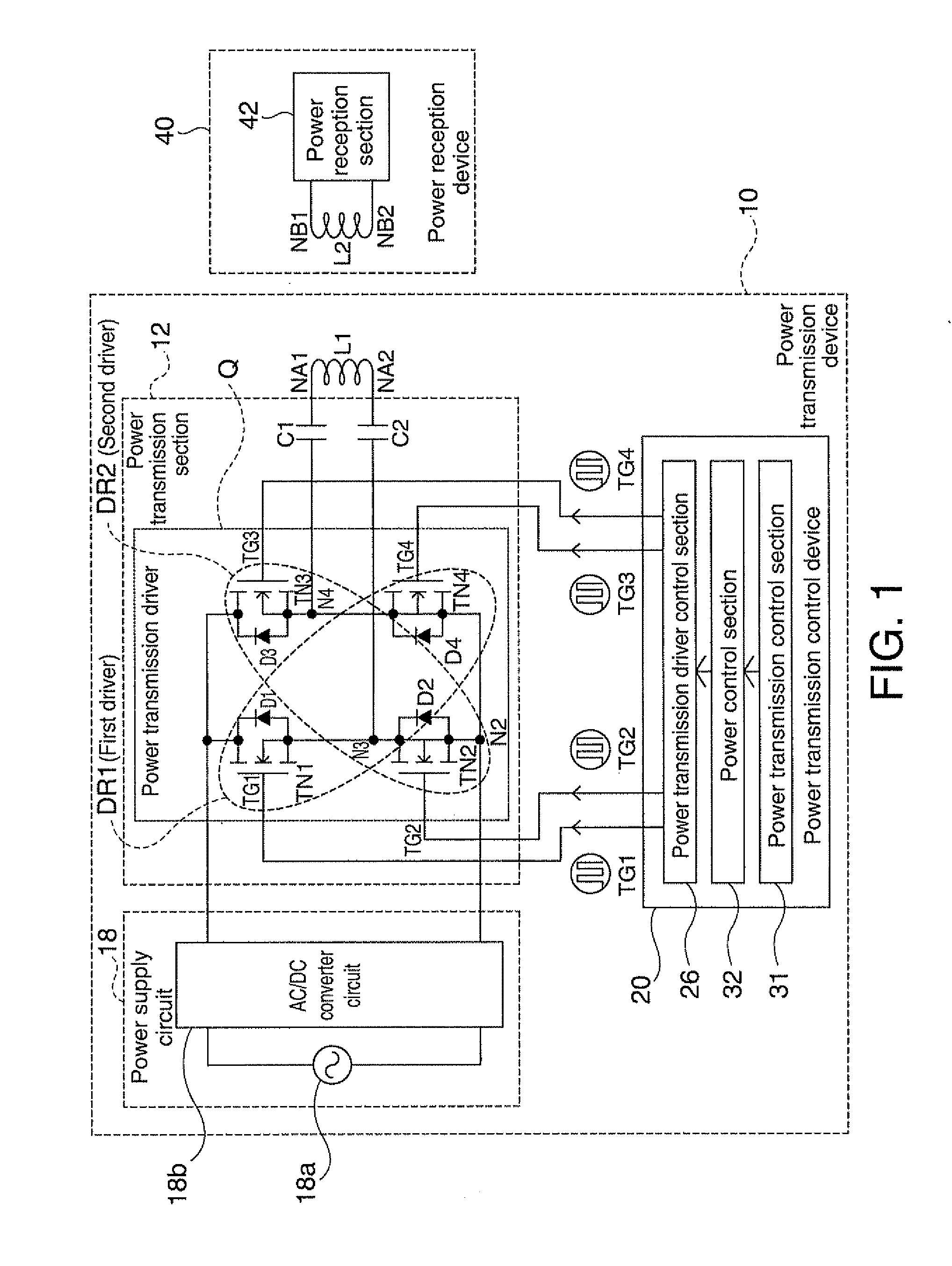
[0063]FIG. 1 is a diagram showing the composition of a power transmission device in accordance with a first embodiment of the invention, and shows a basic exemplary composition of a power transmission control device in accordance with an embodiment of the invention.

[0064]A power transmission device 10 shown in FIG. 1 includes a power supply circuit 18 (having an AC voltage source 18a and an AC / DC converter circuit 18b), a power transmission section 12, and a primary coil L1. Also, a power reception device 40 includes a secondary coil L2 and a power reception sec...

second embodiment

[0097]FIG. 6 is a diagram showing another example of a power transmission device (including a power transmission control device) in accordance with an embodiment of the invention (an example in which zero-voltage switching is performed). The power transmission device 10 in accordance with the present embodiment is provided with, in addition to the circuit composition shown in FIG. 1, capacitors for zero-voltage switching (adjustment capacitors) CB1-CB4 (the capacitors are encircled by a thick dotted line in FIG. 6).

[0098]The zero-voltage switching capacitors (adjustment capacitors) CB1 and CB2 and the zero-voltage switching capacitors CB3 and CB4 are connected in series between the high potential power supply and the low potential power supply, respectively. A common connection node of the CB1 and the CB2 is connected to a common connection node N3 between the first transistor TN1 and the second transistor TN2. A common connection node of the CB3 and the CB4 is connected to a common...

third embodiment

[0102]FIG. 8 is a diagram showing an example of a contactless power transmission system in accordance with an embodiment of the invention (an example in which information is fed back from the power reception device side to the power transmission device side). In accordance with the present embodiment, the power reception device 40 transmits feedback information to the power transmission device 10, and the power transmission device 10 adaptively changes the transmission power based on the received feedback information.

[0103]In FIG. 8, the power reception device 40 further includes a load information detection circuit 47 for detecting load information of the load 90. The power reception device 40 transmits load information as feedback information to the primary side through normal communication from the secondary side coil L2 to the primary side coil L1 by a load modulation.

[0104]On the other hand, the power transmission control device 20 includes a reception processing section 34 tha...


PUM


Abstract

A power transmission control device controls a power transmission device in a contactless power transmission system that transmits power from the power transmission device to a power reception device through electromagnetically coupling a primary coil and a secondary coil. The power transmission control device includes a power transmission driver control section that controls drive timings of a plurality of switching elements of a power transmission driver that drives the primary coil, the power transmission driver control section variably controlling the power to be transmitted from the power transmission device to the power reception device.

Description

[0001]The present application claims a priority based on Japanese Patent Application No. 2009-55102 filed on Mar. 9, 2009, the contents of which are incorporated herein by reference.BACKGROUND[0002]1. Technical Field[0003]The present invention relates to power transmission control devices, power transmission devices, power reception control devices, power reception devices, electronic apparatuses, and contactless power transmission systems.[0004]2. Related Art[0005]In recent years, contactless power transmission (non-contact power transmission) which utilizes electromagnetic induction to enable power transmission without metal-to-metal contact has been attracting attention. Among application examples of contactless power transmission, an application thereof to charging a portable telephone, a household appliance (for example, telephone handset), and the like has been proposed.[0006]When a contactless power transmission system is to be put in practical use, a reduction of power consu...

Claims


Application Information

Patent Timeline
Patent Type & Authority Applications(United States)
IPC IPC(8): H02J17/00H02J7/10H02J7/00
CPCH02M3/337H02J5/005H02J7/00045H02J50/80H02J50/12H02J50/60H02J7/0049H02M3/33573
Inventor AOYAMA, TAKASHISOGABE, HARUHIKO
Owner SAMSUNG ELECTRONICS CO LTD
Why Eureka
Try Eureka