Partitioned implantable system

a technology of implantable components and parts, applied in the field of fully implantable devices or systems, can solve the problems of troublesome and inconvenient maintenance of the coupling between the external components and the implanted components, inability to fully implant, etc., to achieve the effect of facilitating the upgrading circuit function

Inactive Publication Date: 2006-05-30
ADVANCED BIONICS AG
View PDF17 Cites 123 Cited by
  • Summary
  • Abstract
  • Description
  • Claims
  • Application Information

AI Technical Summary

Benefits of technology

[0012]A key feature of the invention relates to housing the system components in two or more detachable modules. The use of detachable modules facilitates upgrading circuit functions, adapting the system to a range of applications and sizes, and / or replacing, through minimal invasive surgery, the battery or power source used within the system.

Problems solved by technology

Disadvantageously, each of the known prior art cochlear stimulation systems, except those that are fully implantable, requires the use of an external power source and speech processing system, coupled to the implanted stimulation device.
For many patients, achieving and maintaining the required coupling between the external components and the implanted component can be troublesome, inconvenient, and unsightly.
This is because the curvature and thickness of the skull is such that there is only a limited amount of space wherein a surgeon may form a pocket wherein a cochlear stimulator may be implanted.
This is particularly an acute problem for young children, where the thickness of the skull is relatively thin and the curvature of the skull is greater than for an adult.

Method used


Image

  • Partitioned implantable system
  • Partitioned implantable system
  • Partitioned implantable system

Examples


embodiment 130

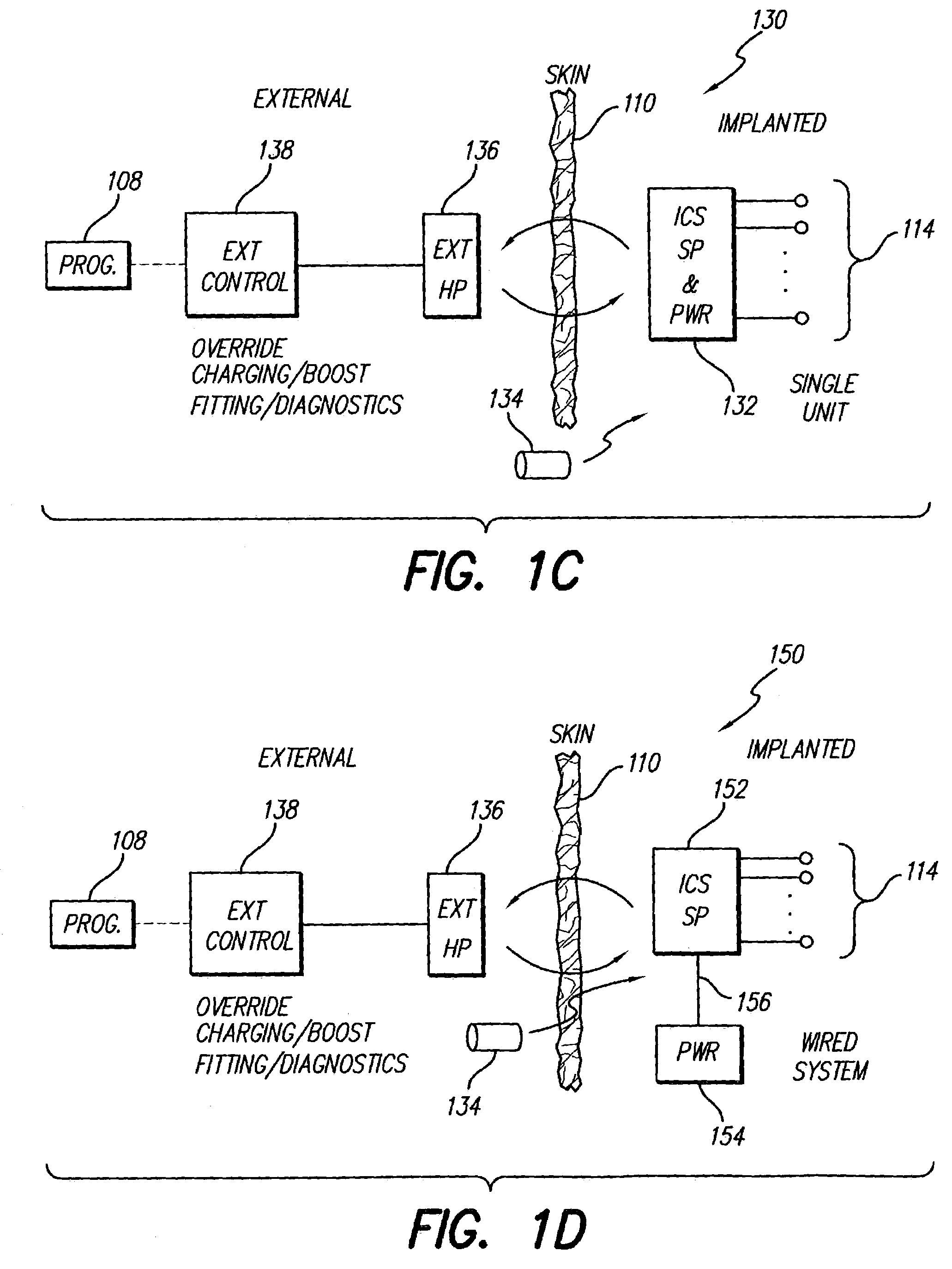
[0044]For the embodiment 130 shown in FIG. 1C, as well as for the other embodiments shown in FIGS. 1D and 1E, discussed below, it is to be understood that backtelemetry may be employed to allow data signals to be sent from the implanted unit to the external headpiece 136, and hence to the external control unit 138.

embodiment 150

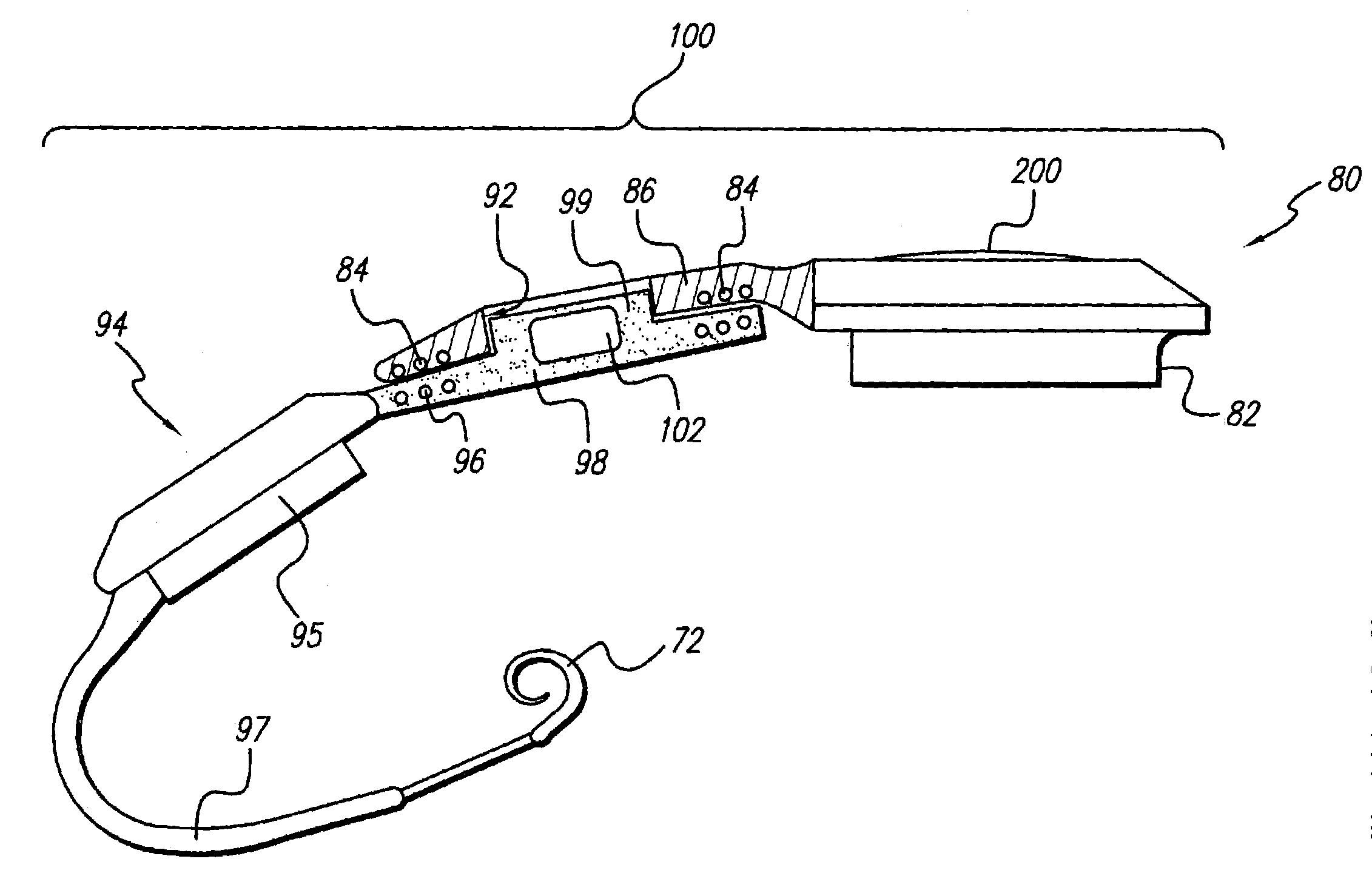
[0045]Turning next to FIG. 1D, a “wired system” embodiment 150 is depicted. In such wired system 150, at least two separate implantable units 152 and 154 are employed and the circuits of the system are partitioned between the two units. In a first unit 152, for example, speech processor (SP) and ICS circuitry are housed, and such unit is permanently connected to an electrode array 114. In a second unit 154, a battery, or other suitable power source, is housed. The second unit 154 is electrically connected to the first unit 152 via a detachable cable 156. Other embodiments of the partitioned system may, as explained below, place the ICS circuitry in one unit, and the SP and battery in the other unit. Preferably, only ac power should be coupled from the power unit 154 to the other unit 152, thereby preventing any possibility that a dc current might flow through the tissue through which the cable is routed. This is important because a dc current could cause damage to the tissue, wherea...


PUM


Abstract

An implantable system includes a plurality of implantable devices that are detachably coupled to each other. Each implantable device of the system includes: (1) an hermetically-sealed case housing electronic components; (2) feedthru terminals mounted to a wall of the hermetically-sealed case adapted to allow electrical contact from a location outside the hermetically-sealed case with the electronic components housed inside the hermetically-sealed case; (3) a coil external to the hermetically-sealed case attached to the feedthru terminals; (4) a flexible molding bonded to the hermetically-sealed case, and wherein the coil is embedded within or otherwise attached to the flexible molding; and (5) engagement means for engaging the flexible molding with a flexible molding of another implantable device of the implantable system. Such engagement means also aligns the coils of the implantable devices that are thus engaged with the engaging means to allow electromagnetic coupling to occur between the aligned coils. In one embodiment, the engaging means includes a hole formed in the flexible molding of a first implantable device and a knob portion formed in the flexible molding of a second implantable device, wherein the knob portion is sized to fit within the hole, and wherein when the knob portion is placed within the hole, the coil of the first device is coaxially aligned with the coil of the second implantable device.

Description

[0001]The present application is a continuation-in-part (C.I.P.) of U.S. patent application Ser. No. 10 / 038,041, filed 2 Jan. 2002, to be abandoned.FIELD OF THE INVENTION[0002]The present invention relates to implantable devices and systems, and more particularly, to a fully implantable device or system for stimulating or sensing living tissue, or for performing some other therapeutic function, wherein the implantable device or system includes partitioning the circuit functions within the implantable system in separate modules.BACKGROUND OF THE INVENTION[0003]Presently available implantable stimulation devices, such as a cochlear implant device or a neural stimulator, typically have an implanted unit, an external ac coil, and an external control unit and power source. The external control unit and power source includes a suitable control processor and other circuitry that generates and sends the appropriate command and power signals to the implanted unit to enable it to carry out it...

Claims


Application Information

Patent Timeline
Patent Type & Authority Patents(United States)
IPC IPC(8): A61N1/00H04R25/00
CPCH04R25/606H04R2410/00H04R2225/67
Inventor KUZMA, JANUSZ A.FALTYS, MICHAEL A.
Owner ADVANCED BIONICS AG
Why Eureka
Try Eureka