
Electromagnetically coupled interconnect system

a technology of electromagnetic coupling and interconnection system, which is applied in the direction of near-field systems using receivers, sustainable manufacturing/processing, instruments, etc., can solve the problems of capacitive electrostatic discharge protection devices, large power consumption, and inability to withstand high frequency signals

Inactive Publication Date: 2005-04-19
FORMFACTOR INC
View PDF43 Cites 124 Cited by
  • Summary
  • Abstract
  • Description
  • Claims
  • Application Information

AI Technical Summary

Benefits of technology

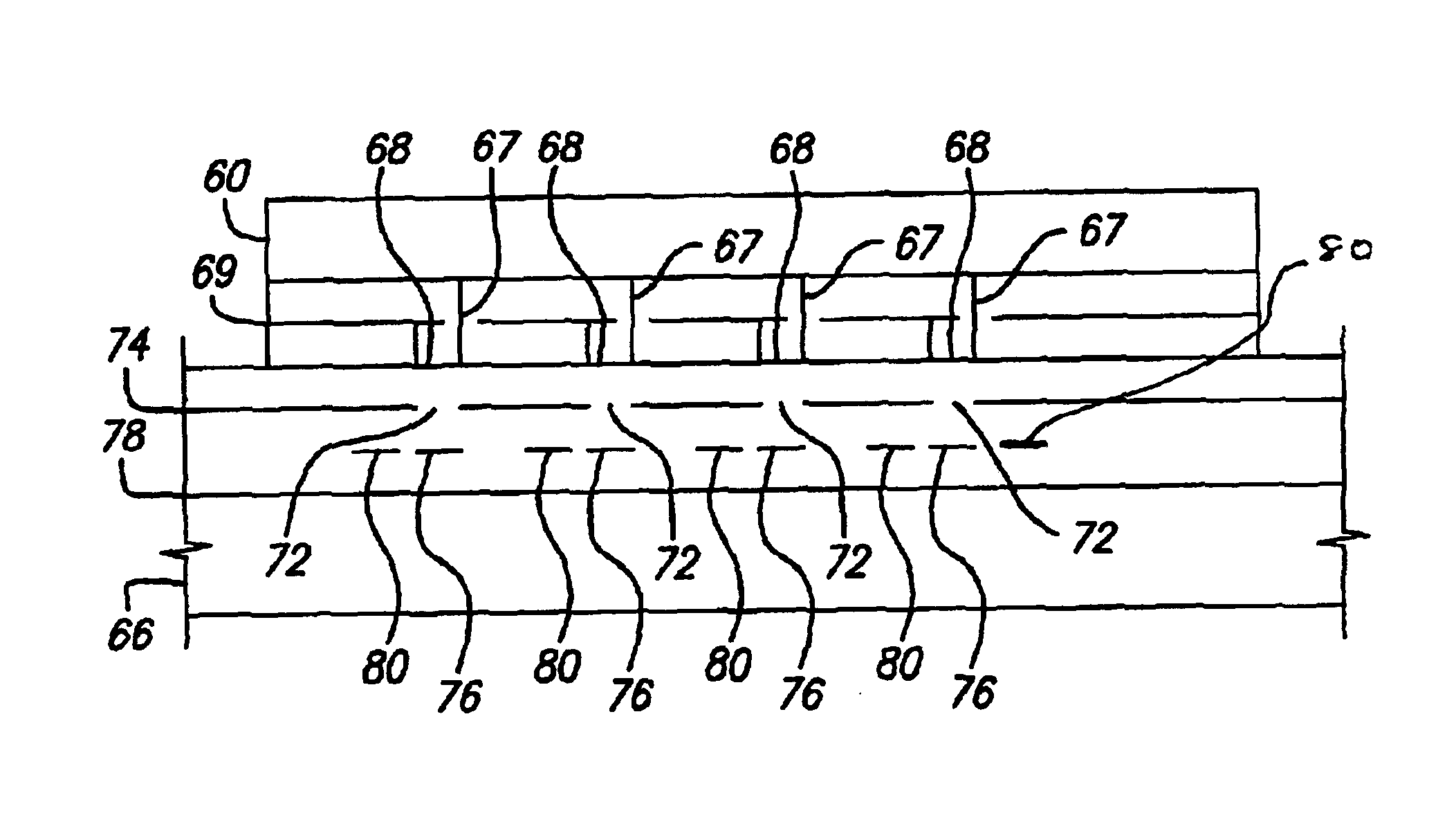
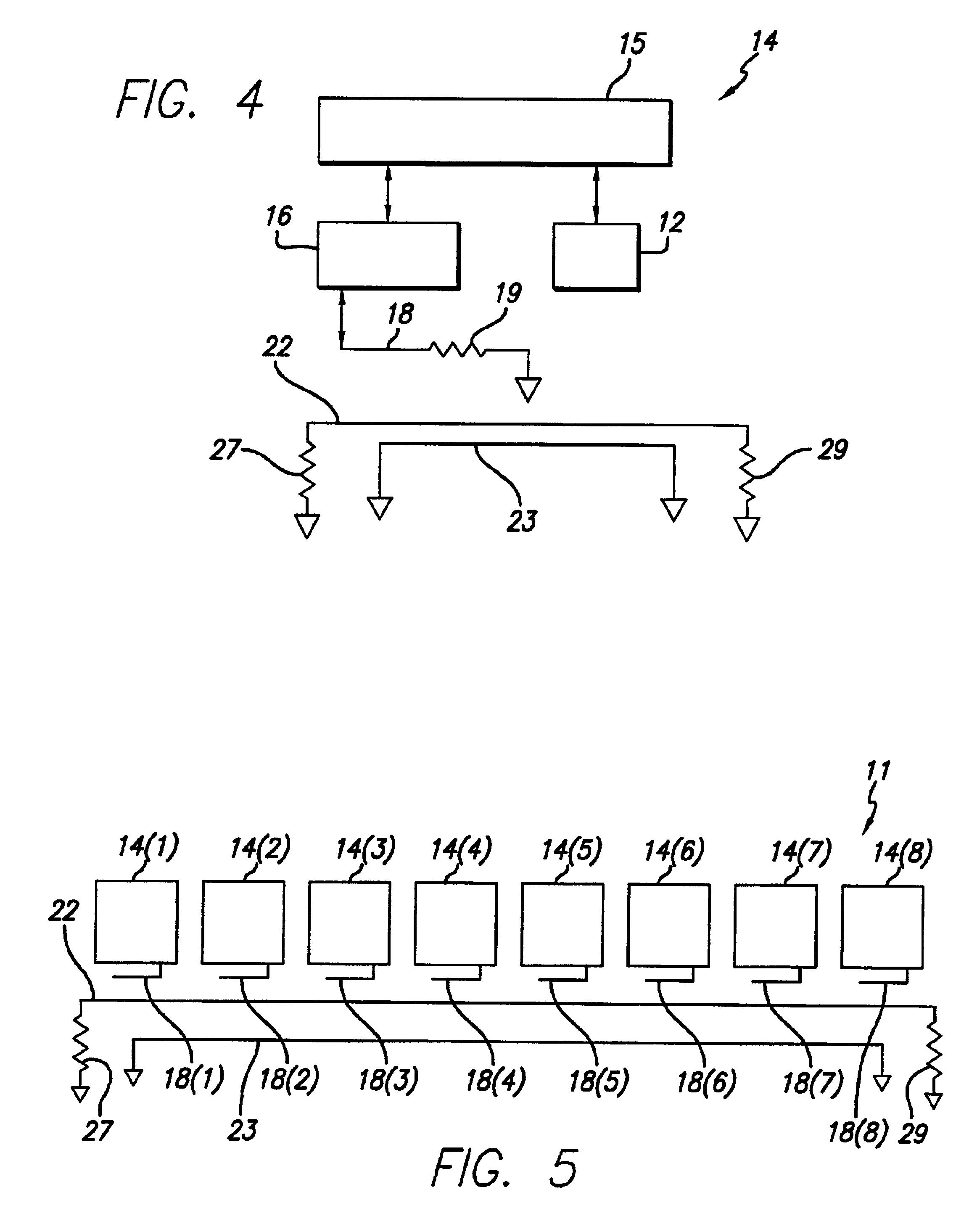
[0008]In one embodiment, a plurality of electronic components, such as integrated circuits, are electromagnetically coupled to a transmission line. A first electronic component modulates data to be sent to another electronic component. The modulated data signal is communicated from the first electronic component to the transmission line and then from the transmission line to the other electronic component by electromagnetic coupling, obviating the need for physical contact between either electronic component and the transmission line. In other embodiments, electronic components, such as integrated circuits, are electromagnetically coupled to each other directly, obviating the need for an intermediary, such as a transmission line.

Problems solved by technology

Such prior methods, however, have several disadvantages: they are costly, they consume power, they can distort and attenuate high frequency signals, and they often require large, capacitive electrostatic discharge (ESD) protection devices.
In many high frequency applications, the signal distortion caused by the wired interconnection structure, rather than the speed of the integrated circuits or system elements themselves, often limits the speed or data rate at which the integrated circuits and system elements are able communicate with each other.

Method used


Image

  • Electromagnetically coupled interconnect system
  • Electromagnetically coupled interconnect system
  • Electromagnetically coupled interconnect system

Examples


Embodiment Construction

[0028]The present invention is directed to a method and apparatus for effecting contactless, proximity connections between elements in an electronics system. (As used herein, “contactless” refers to a lack of a direct physical or mechanical contact through which electrons can flow, i.e., “contactless” means that direct electrical contact between conductors is not required.) The following describes exemplary embodiments of the invention. The invention, however, is not limited to the following exemplary embodiments or to the manner in which the exemplary embodiments operate or are described herein.

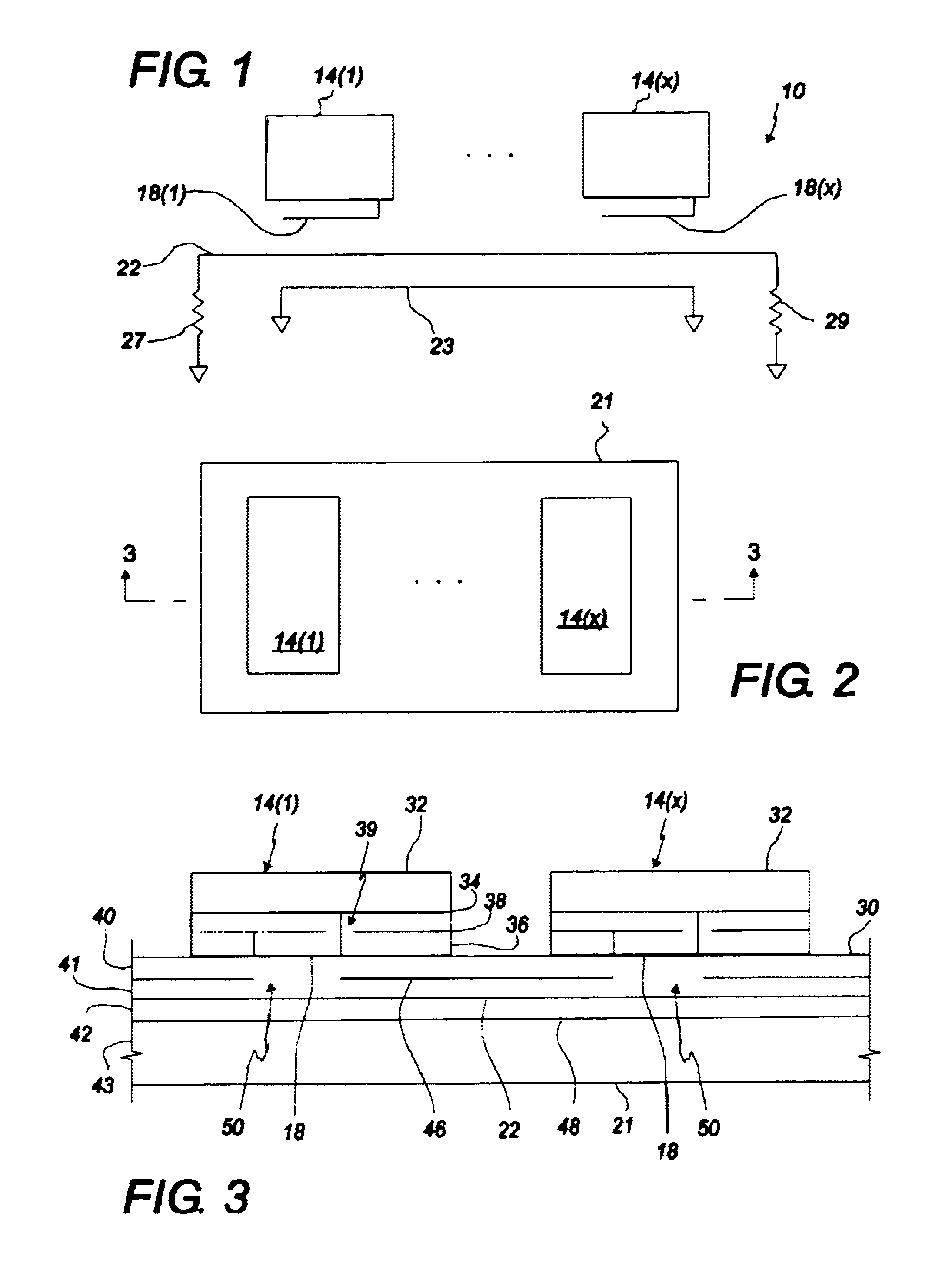
[0029]FIGS. 1 through 4 illustrate an exemplary embodiment of the invention. As shown in FIG. 1, an electronics system 10 includes a plurality of integrated circuits 14(1)-14(x) and a transmission line 22. As shown in FIG. 1, a transmission line typically includes return line 23. As illustrated in FIGS. 2 and 3, the integrated circuits 14(1)-14(x) are mounted on a printed circuit board 21, a...


PUM


Abstract

An electromagnetic interconnect method and apparatus effects contactless, proximity connections between elements in an electronics system. Data to be communicated between elements in an electronic system are modulated into a carrier signal and transmitted contactlessly by electromagnetic coupling. The electromagnetic coupling may be directly between elements in the system or through an intermediary transmission medium.

Description

BACKGROUND OF THE INVENTION[0001]1. Field of the Invention[0002]The present invention relates in general to an electromagnetic contactless interconnect scheme for providing a communication path between electronic components, such as integrated circuits, and / or electrical systems and, in particular, to an electrical interconnect scheme in which the electronic elements are electromagnetically coupled to each other either directly or through an intermediate device, by contactless proximity connections.[0003]2. Description of Related Art[0004]Integrated circuits and other elements of an electronics system typically communicate with one another through a wired interconnection structure. For example, in a data processing or computing system, a parallel wired interface, such as a bus, may link a microprocessor to other integrated circuits, such as memory integrated circuits, within the system. To communicate with one another, all of the integrated circuits and other electronic elements of ...

Claims


Application Information

Patent Timeline
Patent Type & Authority Patents(United States)
IPC IPC(8): H04B5/00H04B5/48
CPCH01L23/48H04B5/0012H04B5/0075H04B5/02H05K1/141H05K1/181H01L2924/3011H01L2924/0002H05K3/366H05K2201/10098H01L2924/00Y02P70/50H04B5/22H04B5/24H04B5/48G06F13/40H04B5/00
Inventor MILLER, CHARLES A.
Owner FORMFACTOR INC
Learn More