Light source device, optical scanning device, and image forming apparatus

Active Publication Date: 2009-12-10
RICOH KK
View PDF26 Cites 24 Cited by
  • Summary
  • Abstract
  • Description
  • Claims
  • Application Information

AI Technical Summary

Benefits of technology

[0011]It is an object of the present invention to at least

Problems solved by technology

If the temperature of the light source increases due to the heating of the drive circuit, this may shorten the lifetime of the VCSEL because the VCSEL is weak against heat compared with the edge emitting semiconductor laser, and cause degradation of the image quality.
However, the cooling devices disclosed in Japanese Patent Application Laid-open No. 2001-217366, Japanese Patent Application Laid-open No. 2002-271073 and Japanese Patent Application No. 4087133 become large in size, which is disadvantageous.

Method used


Image

  • Light source device, optical scanning device, and image forming apparatus
  • Light source device, optical scanning device, and image forming apparatus
  • Light source device, optical scanning device, and image forming apparatus

Examples


Embodiment Construction

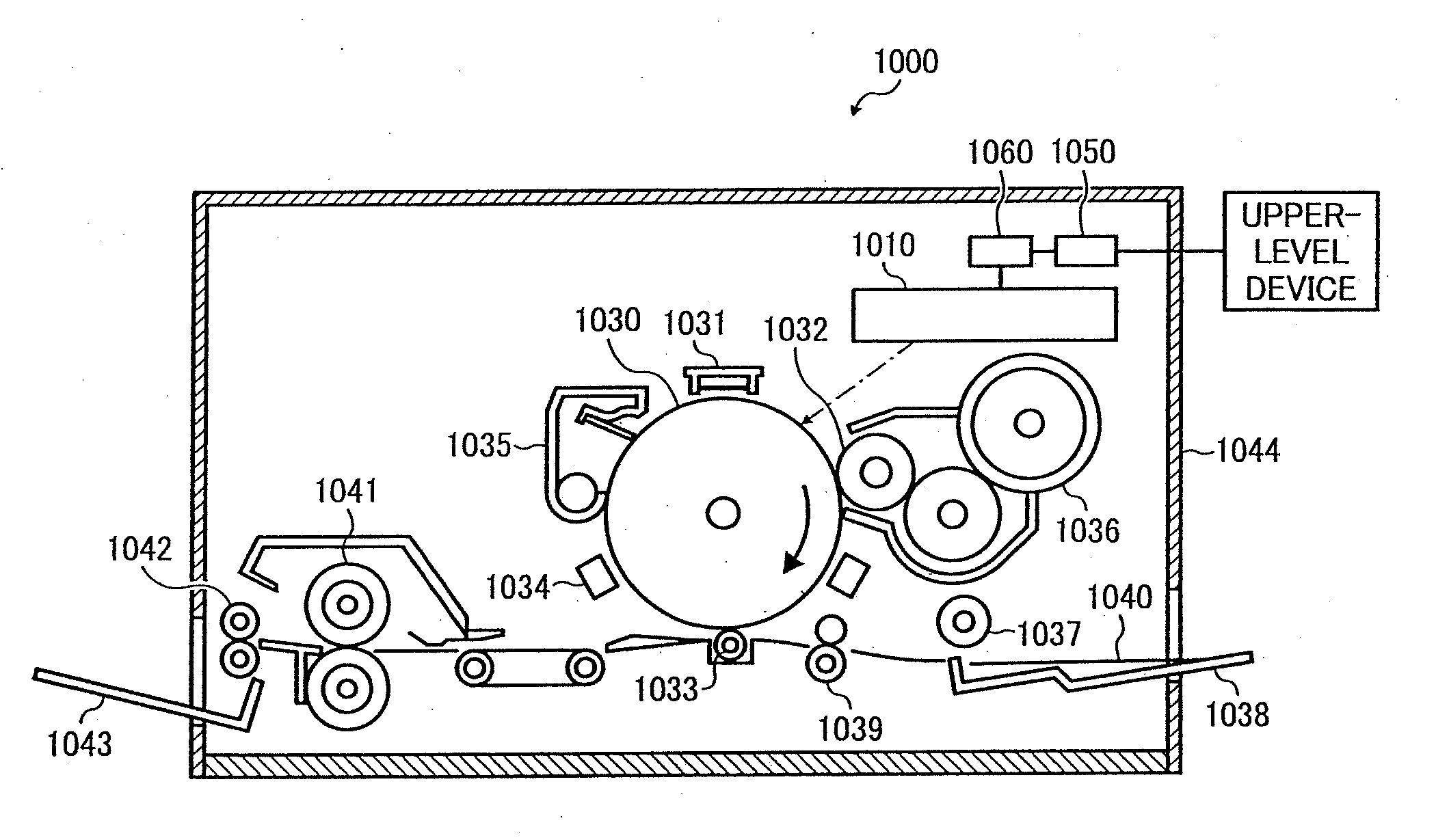
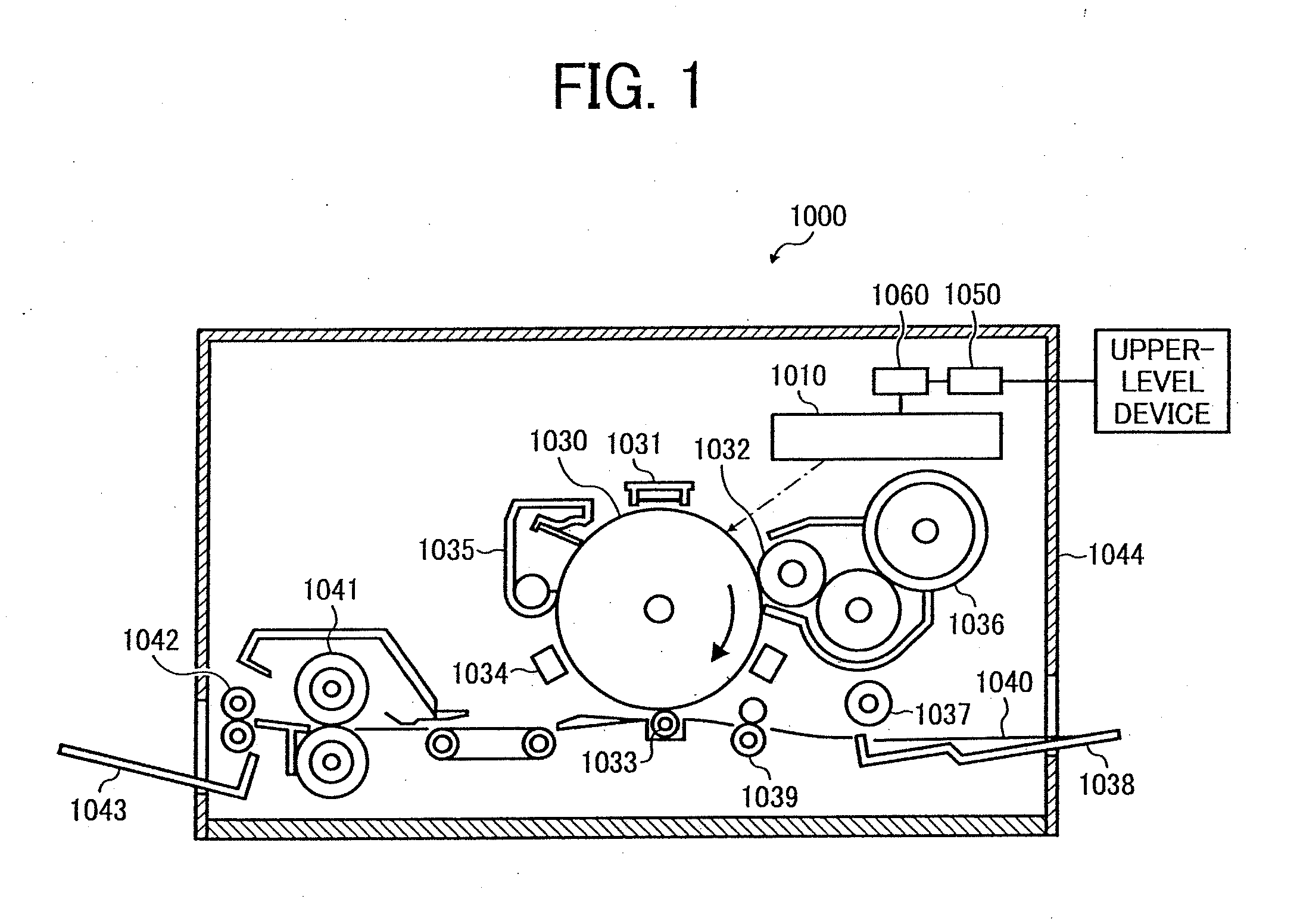
[0035]Exemplary embodiments of the present invention are described in detail below with reference to FIGS. 1 to 15B. FIG. 1 is a schematic diagram of a laser printer 1000 as an image forming apparatus according to an embodiment of the present invention.

[0036]The laser printer 1000 includes an optical scanning device 1010, a photosensitive element 1030, a charging unit 1031, a developing roller 1032, a transfer charging unit 1033, a neutralizing unit 1034, a cleaning unit 1035, a toner cartridge 1036, a sheet feeding roller 1037, a sheet feeding tray 1038, a pair of registration rollers 1039, a fixing roller 1041, a sheet discharging roller 1042, a catch tray 1043, a communication control device 1050, and a printer control device 1060 that controls above-mentioned each unit as a whole. These units are housed in respective predetermined positions in a printer housing 1044.

[0037]The communication control device 1050 controls a two-way communication with an upper-level device (such as a...


PUM


Abstract

A light source device includes a light source that includes a vertical cavity surface emitting laser; a drive circuit that drives the light source; and a circuit board that includes at least one mounting surface on which the light source and the drive circuit are mounted. The light source is mounted on a first area of the mounting surface, the drive circuit is mounted on a second area of the mounting surface, and a highest end of the first area is at a same height or lower than a lowest end of the second area with respect to a gravity direction.

Description

CROSS-REFERENCE TO RELATED APPLICATIONS[0001]The present application claims priority to and incorporates by reference the entire contents of Japanese priority document 2008-151148 filed in Japan on Jun. 10, 2008.BACKGROUND OF THE INVENTION[0002]1. Field of the Invention[0003]The present invention relates to a light source device, an optical scanning device, and an image forming apparatus.[0004]2. Description of the Related Art[0005]In recent years, in an image forming apparatus such as a laser printer and a digital copying machine, there is an increasing demand for high-speed and high-density printing. A semiconductor laser is generally employed as a light source, and recently, a vertical cavity surface emitting laser (hereinafter, “VCSEL”) has been used in addition to an edge emitting semiconductor laser that was used more commonly.[0006]On the other hand, with the advancement of the high-speed and high-density printing, the heating value generated in a drive circuit that supplies ...

Claims


Application Information

Patent Timeline
IPC IPC(8): G03B27/52F21V19/00G02B27/20
CPCG02B26/125G03G15/0435G03G15/04072G03G15/326
Inventor MIYAKE, SHINSUKEOMORI, ATSUFUMI
Owner RICOH KK
Why Eureka
Try Eureka