LED Lighting Device

a technology of led lighting and led tubes, which is applied in the direction of lighting support devices, semiconductor devices for light sources, lighting and heating apparatus, etc., can solve the problems of phosphors presenting toxic waste situations, tubes which have ceased to function, and use rare earth and other toxic phosphors to generate light, etc., to achieve convenient breakage and increase the useful life of devices

Inactive Publication Date: 2009-12-10
LEDDYNAMICS
View PDF89 Cites 94 Cited by
  • Summary
  • Abstract
  • Description
  • Claims
  • Application Information

AI Technical Summary

Benefits of technology

[0010]In yet still another implementation, no glass or other easily breakable materials are utilized and no toxic substances are used. Therefore, there is no need for heat trapping protective sleeves or other covering devices to be used. A further implementation provides for means to remove the heat generated by the LEDs and thereby increase the useful life of the devices. In still a further implementation, the filter capacitance at the input offsets, to some degree, the inductive load presented by the ballast and bring the input power factor closer to unity.

Problems solved by technology

One significant drawback is their use of rare-earth and other toxic phosphors to generate light.
This provides a problem when tubes which have ceased to function require disposal.
The phosphors can present a toxic waste situation which must be dealt with.
Also, because the envelope of the tube is thin glass, the potential for accidental breakage, with attendant problems of scattering toxic material, is high.
A drawback to the use of these sleeves is that they trap heat generated by the tube and increase the operating temperature of the tube which decreases the useful life of the device.
The ballasts used in fluorescent fixtures present an inductive load to the line resulting in a lower than unity power factor.
While fluorescent lighting is longer lasting and more efficient than incandescent bulbs, the tubes have a short life relative to solid state lighting devices.
Heretofore, tubes meant to accomplish this were unable to work with standard magnetic or electronic ballasts, and required replacement or complete rewiring of the lighting fixture.

Method used


Image

  • LED Lighting Device
  • LED Lighting Device
  • LED Lighting Device

Examples


Embodiment Construction

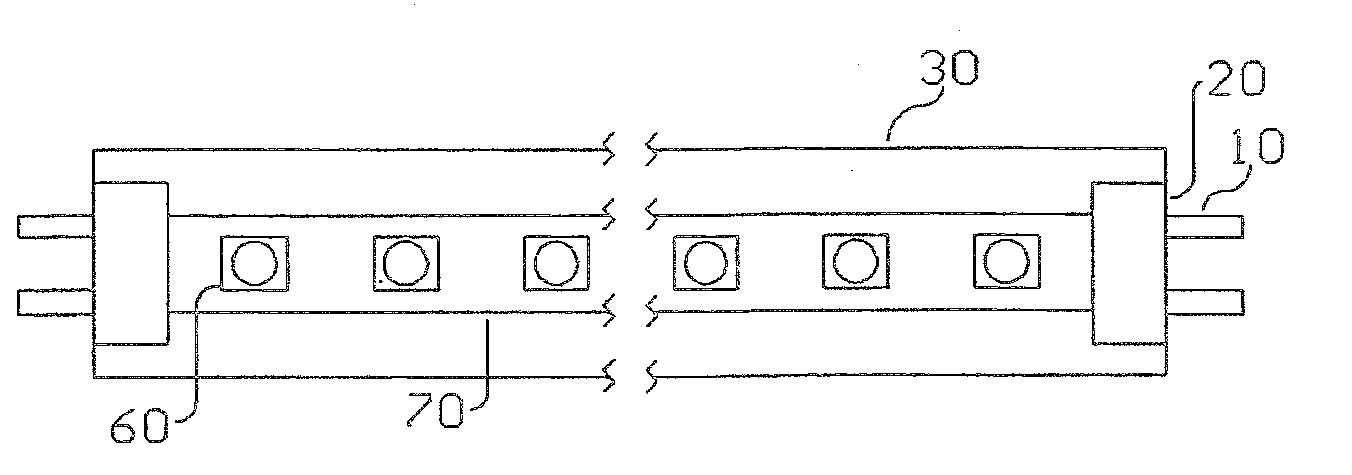
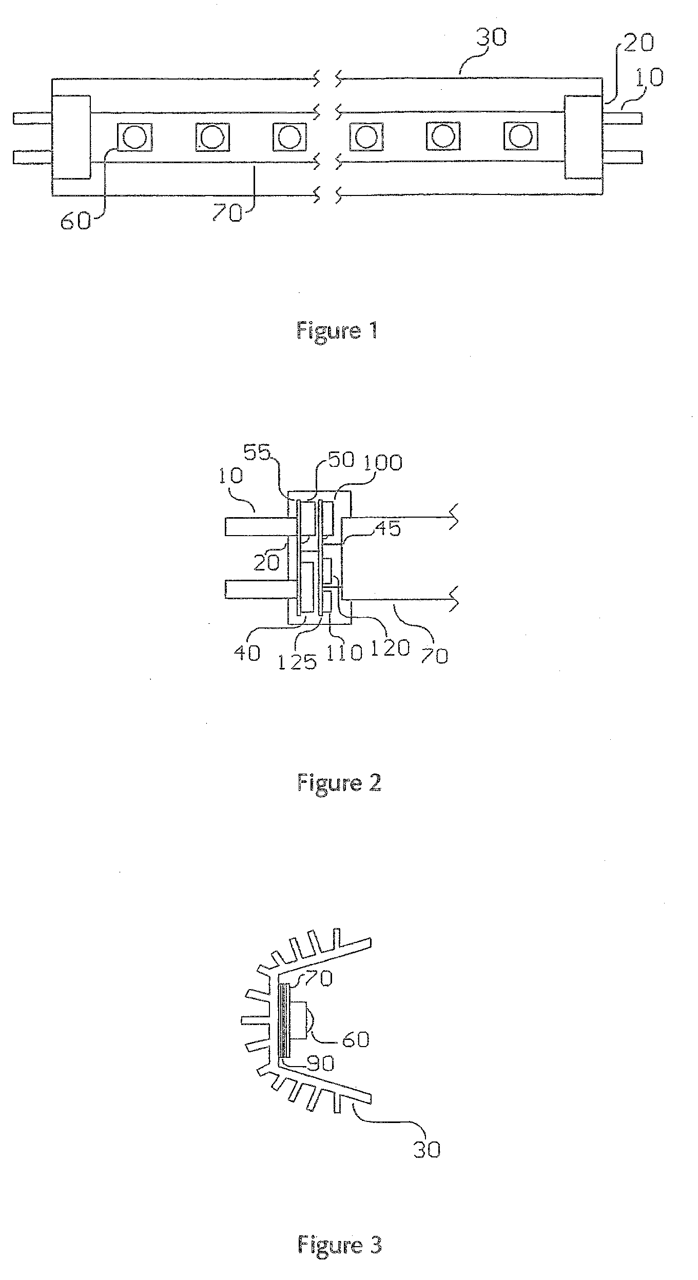
[0055]Referring now to the drawings, FIG. 1 shows a plan view of an embodiment of the present invention. A multiplicity of LEDs 60 are mounted to the LED circuit board 70 and attached to two end caps 20. This assembly is mounted to heat sink 30 which also acts as a protective housing. The end caps 20 are fitted with contact pins 10, spaced such that they mate with standard fluorescent fixture connectors. The overall length of the assembly is equivalent to that of a standard fluorescent tube.

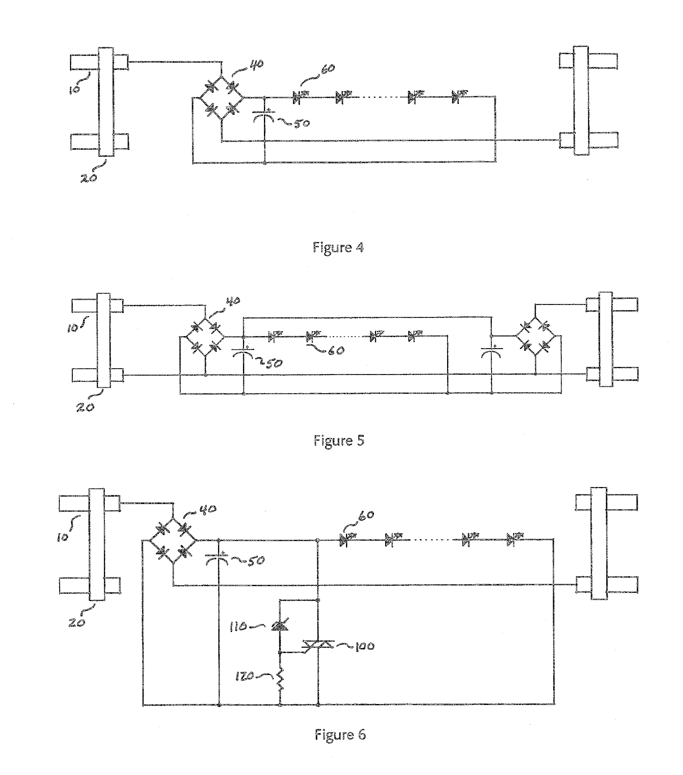
[0056]FIG. 2 is a cross-sectional of an end cap 20. Contact pins 10 are physically and electrically connected to the input circuit board 55 upon which are mounted the rectifier bridge 40 and capacitor 50. The input circuit board 55 is physically and electrically connected to the control circuit board 125 by bus wires 45. The shut down triac 100, overvoltage sense Zener diode 110, and current setting resistor 120 are mounted on control circuit board 125. These components are from the embodiment sh...


PUM


Abstract

An arrangement of a multiplicity of LEDs, drive circuitry, and supporting structure to form a replacement for standard fluorescent tubes without the need to rewire or remove the magnetic or electronic ballasts in use in standard fluorescent fixtures.

Description

RELATED APPLICATION DATA[0001]This application is a continuation application of U.S. patent application Ser. No. 11 / 361,656, filed Feb. 23, 2006 entitled “Circuit Devices Which Include Light Emitting Diodes, Assemblies Which Include Such Circuit Devices, and Methods for Directly Replacing Fluorescent Tubes,” which is incorporated herein by reference in its entirety. This application claims the benefit and priority of U.S Provisional Application Ser. No. 60 / 657,100 filed Feb. 28, 2005 entitled “Fluorescent Replacement Using Light Emitting Diodes,” which is incorporated herein by reference in its entirety.FIELD OF THE INVENTION[0002]The present invention relates to a circuit device for providing energy to a series of light emitting diodes and an assembly including such circuit devices and light emitting diodes. The present invention relates to a light emitting diode (LED) assembly for direct replacement of a tubular fluorescent light bulb.BACKGROUND[0003]The widespead use of fluoresce...

Claims


Application Information

Patent Timeline
Patent Type & Authority Applications(United States)
IPC IPC(8): F21S4/00
CPCF21K9/17F21Y2101/02F21Y2103/003Y02B20/386H05B33/0809H05B33/0848H05B33/0803F21K9/278F21Y2103/10F21Y2115/10H05B45/14H05B45/325H05B45/3578H05B45/56H05B47/20Y02B20/30F21K9/27
Inventor MCGRATH, WILLIAM R.
Owner LEDDYNAMICS
Why Eureka
Try Eureka