
Lamp with a box-like lamp housing element and a light outlet element

a technology of light outlet element and lamp housing element, which is applied in the field of luminaire, can solve the problems of soiling of the region around the luminaire raster provided for the directional issue of light, and achieve the effects of simple cleaning, advantageous lighting technical qualities, and high maintenance factor

Active Publication Date: 2009-12-10
ZUMTOBEL LIGHTING GMBH & CO KG
View PDF18 Cites 5 Cited by
  • Summary
  • Abstract
  • Description
  • Claims
  • Application Information

AI Technical Summary

Benefits of technology

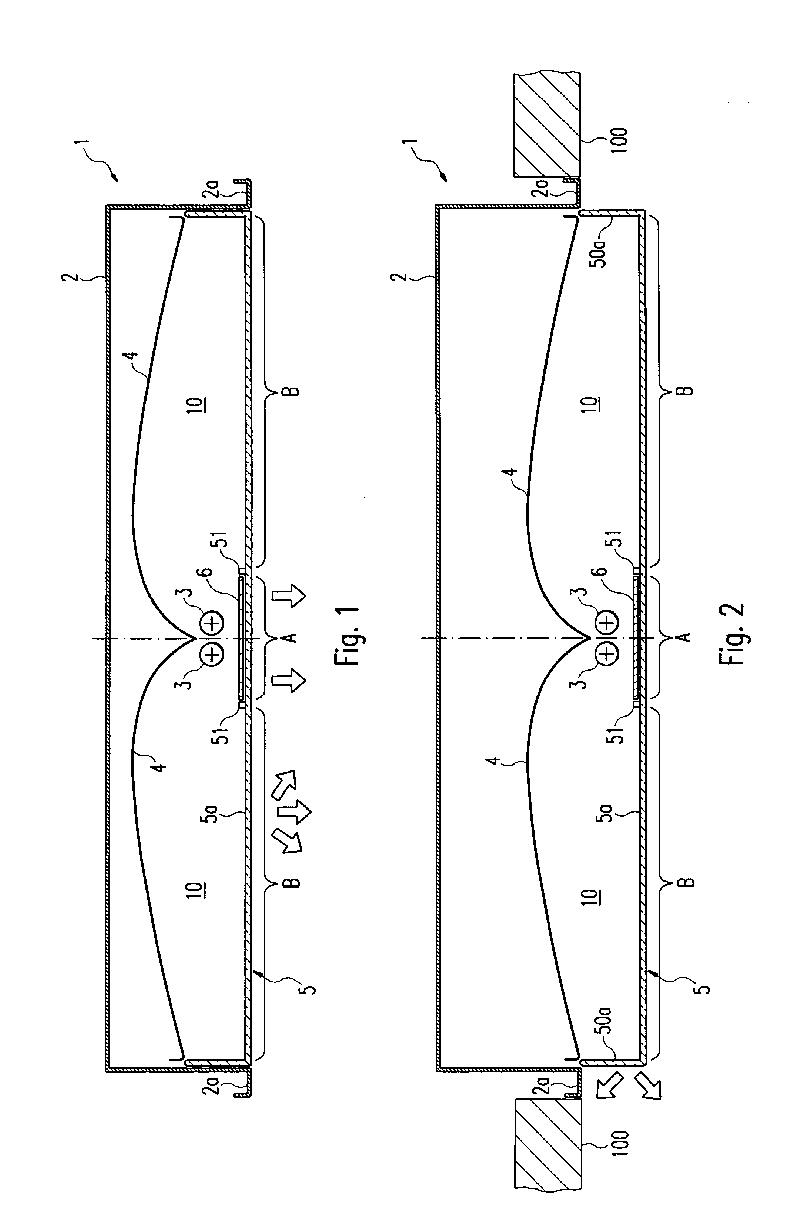
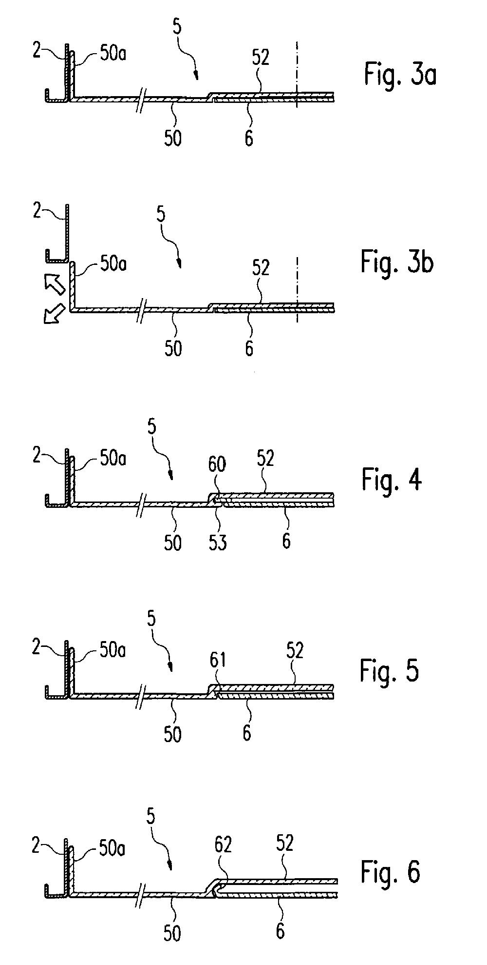
[0008]The ranges of application of the luminaire in accordance with the invention can further be improved in accordance with a further development of the present invention in that the light exit element is adjustable in light emission direction. In this case there is in particular the possibility of allowing the light exit element to project slightly with respect to the the luminaire housing. Through this the possibility is opened up of issuing light via side wall regions of the light exit element also to the side and additionally brightening the ceiling region surrounding the luminaire. The lighting technical qualities of the luminaire in accordance with the invention are correspondingly further improved. Thereby it can in particular be provided that the light exit element forms a unit with the light source and the reflector surface which is adjustable in common with respect to the luminaire housing. In this way it is ensured that the arrangement of light source(s), reflector surface(s) and light exit element with respect to one other always remains the same.
[0009]As already mentioned, the light exit element used in the case of the luminaire in accordance with the invention is preferably configured such that the light leaving the luminaire via the first emission region of the light exit element is emitted solely in a determined angular range, thus is emitted directionally. In this way a dazzle-free illumination of the room lying below the luminaire is attained. The luminaire in accordance with the invention is thus in particular suitable also for use at display workstations at which reflections on the surface of a screen or the like are to be avoided.
[0011]The concept already mentioned above, of so forming light exit element that it is adjustable with respect to the luminaire housing in light emission direction, can also be used independently of whether or not the light exit element has different light emission characteristics in different regions. Independently thereof, namely, the advantage is obtained that with a position of the light exit element at which it slightly projects with respect to the luminaire housing, the ceiling region surrounding the recessed lamp is brightened.
[0014]Thus in accordance with this third aspect of the invention there is proposed a luminaire having a box-like luminaire housing for receiving at least one elongate light source and at least one reflector surface arranged—seen from the region to be illuminated—neighbouring the light source, wherein the luminaire housing forms a light exit opening which is closed by a light exit element and wherein in accordance with the invention it is provided that the light exit element is of a plurality of part elements, wherein a first part element is arranged in substance in front of the light source and a second part element is arranged in substance in front of the reflector surface, and wherein the first and / or the second part element is adjustable seen in light emission direction. The first part element has preferably a first light emission characteristic and the second part element has a second light emission characteristic different with respect to the first light emission characteristic, so that in turn the possibility of a directional issue of light and a supplementary diffuse illumination is made possible.
[0016]Overall, through the present invention, a new luminaire concept is proposed which leads to a luminaire which can be cleaned simply with a high maintenance factor, and particularly advantageous lighting technical qualities.

Problems solved by technology

In turn this has the consequence that in particular the region around the luminaire raster provided for directional issue of light is susceptible to soiling.

Method used


Image

  • Lamp with a box-like lamp housing element and a light outlet element
  • Lamp with a box-like lamp housing element and a light outlet element
  • Lamp with a box-like lamp housing element and a light outlet element

Examples


Embodiment Construction

[0024]In the case of recessed ceiling luminaire illustrated in FIG. 1 and provided overall with the reference sign 1 the different components of the luminaire 1 are arranged within a box-like luminaire housing 2, which upon installation of the luminaire 1 is recessed into the ceiling of the room to be illuminated. For this purpose the luminaire housing 2 has edge strips 2a projecting at the side, which when placing the housing 2 into a mounting opening of the ceiling come to bear against the ceiling and completely close the mounting opening. These edge strips 2a may also further have—not illustrated—mountings which make possible an adaptation to the thickness of the ceiling and correspondingly ensure that the luminaire housing 2 in principle ends flush with the surrounding ceiling.

[0025]Within the housing 2 there are firstly arranged two rod-shaped gas discharge lamps, in particular fluorescent lamps 3, which serve as light sources of the luminaire 1 and extend centrally through the...


PUM


Abstract

A luminaire having a box-like luminaire housing for receiving at least one elongate light source and at least one reflector surface arranged—seen from the region to be illuminated—neighbouring the light source, the luminaire housing forms a light exit opening which is closed by a light exit element. The light exit element has in a first emission region, located in substance in front of the light source, a first light emission characteristic, and has in a second emission region, separate from the first emission region, a second light emission characteristic different with respect to the first light emission characteristic.

Description

TECHNICAL FIELD OF THE INVENTION[0001]The present invention concerns a luminaire which has a box-like luminaire housing for receiving at least one elongate light source and at least one reflector surface arranged—seen from the region to be illuminated—neighbouring the light source, wherein the luminaire housing forms a light exit opening which is closed by a light exit element for the issue of light.BRIEF SUMMARY OF RELATED ART[0002]A comparable luminaire is known from WO 01 / 59364 A1 of the applicant. There is involved here a luminaire which on the one hand issues light directionally—that is, within a determined angular range—and with which, on the other hand, the region of the luminaire provided for the directional issue of light is additionally brightened in its surroundings. For this purpose the known luminaire has additional reflector wings which extend to the side from the light source, in front of which light source—seen in emission direction—there is arranged a raster, and di...

Claims


Application Information

Patent Timeline
IPC IPC(8): F21V17/00
CPCF21S8/02F21V3/04F21V5/002F21V5/02F21V14/06F21Y2103/00F21V17/101F21V17/102F21V17/104F21V17/164F21V17/02
Inventor LADSTATTER, GERALDGASSNER, PATRIKPETSCHULAT, MANFRED
Owner ZUMTOBEL LIGHTING GMBH & CO KG
Learn More