Network element providing an interworking function between plural networks, and system and method including the network element

a network element and interworking function technology, applied in the field of network elements, can solve the problems of limited accuracy of predicting the bandwidth of transport instances and the reduction of service installation tim

Inactive Publication Date: 2009-12-10
NEC CORP
View PDF6 Cites 45 Cited by
  • Summary
  • Abstract
  • Description
  • Claims
  • Application Information

AI Technical Summary

Problems solved by technology

A problem with related art networks (e.g., the network 1001 of FIG. 1) is that since a transport network tends to be managed based on centralized management instead of distributed management, interworking between networks (e.g., a service network such as an IP / MPLS network and a transport network) which is suited to the current management style does not exist.
As a result, reduction of service installation time and accuracy of predicting required bandwidth of transport instances are limited by the manual negotiation between the networks (e.g., between a service network and a transport network).

Method used


Image

  • Network element providing an interworking function between plural networks, and system and method including the network element
  • Network element providing an interworking function between plural networks, and system and method including the network element
  • Network element providing an interworking function between plural networks, and system and method including the network element

Examples


case 1

[0056]In case 1 of FIG. 4, a connection-oriented path 415 maybe set up between NE #1 and NE #5 through NE #2, NE #3 and NE #4. The setup methods of the connection-oriented path include, but are not limited to, manual path setting by the centralized control plane such as NMS, and by automatic setting by the centralized control plane based on policies of network management. Attributes of the connection-oriented path, such as end-points and available bandwidth, may be communicated to routers 430, 435 connected to NE #1 and NE #5, respectively, through routing protocols such as OSPF-TE, and thus human intervention is not required for communicating a change of the connection-oriented path 415.

[0057]Routers 430, 435 which are connected to networks 440 and 445 (e.g., IP / MPLS networks), respectively, and connected to NE #1 and NE #5, respectively, can set up LSPs based on the attributes of the connection-oriented path obtained by the NEs 200. The LSPs may be set up by signaling protocols su...

first embodiment

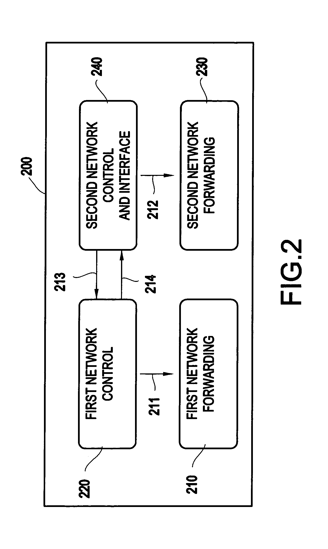
[0071]Similarly to the network element 200 in the first embodiment, in the network element 700, the first network control function block 720 (e.g., a service network control function block such as an IP / MPLS control function block) may control packet forwarding (711) (e.g., IP / MPLS packet forwarding) which is implemented in the first network forwarding function block 710 (e.g., a transport network forwarding function block such as an IP / MPLS forwarding function block, and the second network control function block 740 may control forwarding (712) of frames in the second network.

[0072]However, network element 700 may further include the interworking function block 750 which may provide a service instance and transport instance control function (e.g., a service instance control functionality) for interworking with the first network control function block 720 and the second network control function block.

[0073]The service instance control functionality of network element 700 may be desc...


PUM


Abstract

A network element provides an interworking function between plural networks. The network element includes a first network forwarding function block for forwarding packets in a first network, a first network control function block for controlling the first network forwarding function block, a second network forwarding function block for forwarding frames along a connection-oriented path in a second network, and a second network control function block for controlling the second network forwarding function block.

Description

BACKGROUND OF THE INVENTION[0001]1. Field of the Invention The present invention relates to a network element and, more particularly, a network element providing an interworking function between plural networks.[0002]2. Description of the Related Art[0003]Historically a service network, such as an Internet Protocol / multi-protocol label switching (IP / MPLS) network, and a transport network such as a synchronized optical network / synchronous digital hierarchy (SONET / SDH) or optical transport network (OTN) are independently managed. Operators of service network setup (e.g., prepare) service instances, such as multi-protocol label switching label switched path (MPLS LSP), and route them through transport instances, such as SONET / SDH paths provided by the transport network. Connectivity and bandwidth of the transport instances are negotiated between operators of the service and transport networks.[0004]If the operators of the service network find that additional bandwidth or a new connecti...

Claims


Application Information

Patent Timeline
Patent Type & Authority Applications(United States)
IPC IPC(8): H04L12/56
CPCH04L41/0806H04L41/0853H04L41/0896H04L45/02H04Q2011/0088H04L45/50H04L49/254H04Q11/0062H04Q2011/0079H04L45/125H04L45/03
Inventor KUREBAYASHI, RINTAROSUEMURA, YOSHIHIKOMATSUDA, OSAMU
Owner NEC CORP
Why Eureka
Try Eureka