Coherent Image Formation for Dynamic Transmit Beamformation

a beamformation and coherent image technology, applied in the field of coherent combination of received ultrasound signals, can solve the problems of greater beam group artifacts, loss of signal-to-noise ratio (snr), and greater loss of snr

Active Publication Date: 2009-12-10
SIEMENS MEDICAL SOLUTIONS USA INC
View PDF2 Cites 24 Cited by
  • Summary
  • Abstract
  • Description
  • Claims
  • Application Information

AI Technical Summary

Benefits of technology

[0007]By way of introduction, the preferred embodiments described below include methods, instructions, computer readable media, and systems for retrospective dynamic transmit beamformation in medical ultrasound imaging. Using parallel receive beamformation, sets of data representing locations in at least a common field of view are obtained, each set in response to a transmit with spatially distinct static phase front. The distinct static phase fronts are achieved through delay profiles steering and focusing at different locations. The common field of view receive data are time-aligned and amplitude-weighted for retrospective transmit focusing and retrospective transmit a

Problems solved by technology

However, beam group artifacts and loss of signal-to-noise-ratio (SNR) may result.
For greater numbers of receive beams formed for each transmit beam, a greater

Method used


Image

  • Coherent Image Formation for Dynamic Transmit Beamformation
  • Coherent Image Formation for Dynamic Transmit Beamformation
  • Coherent Image Formation for Dynamic Transmit Beamformation

Examples


Embodiment Construction

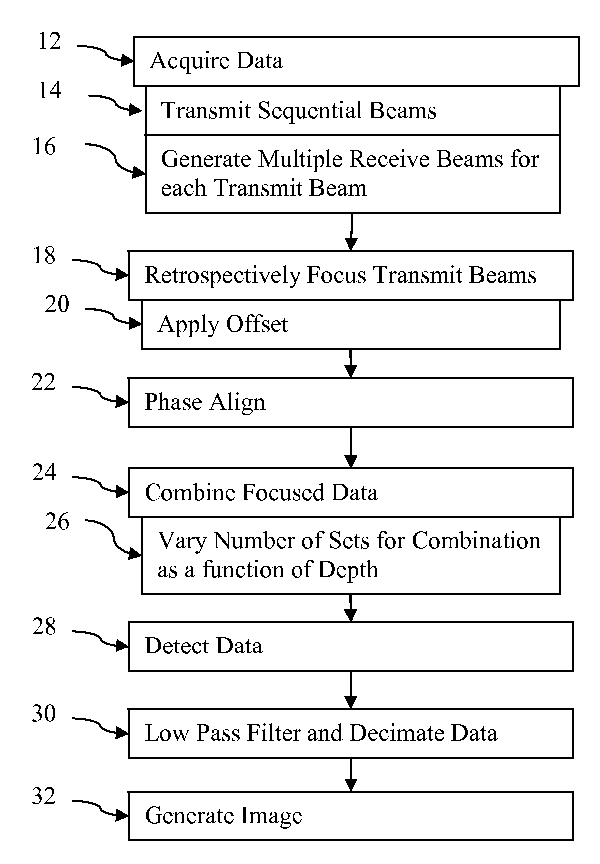
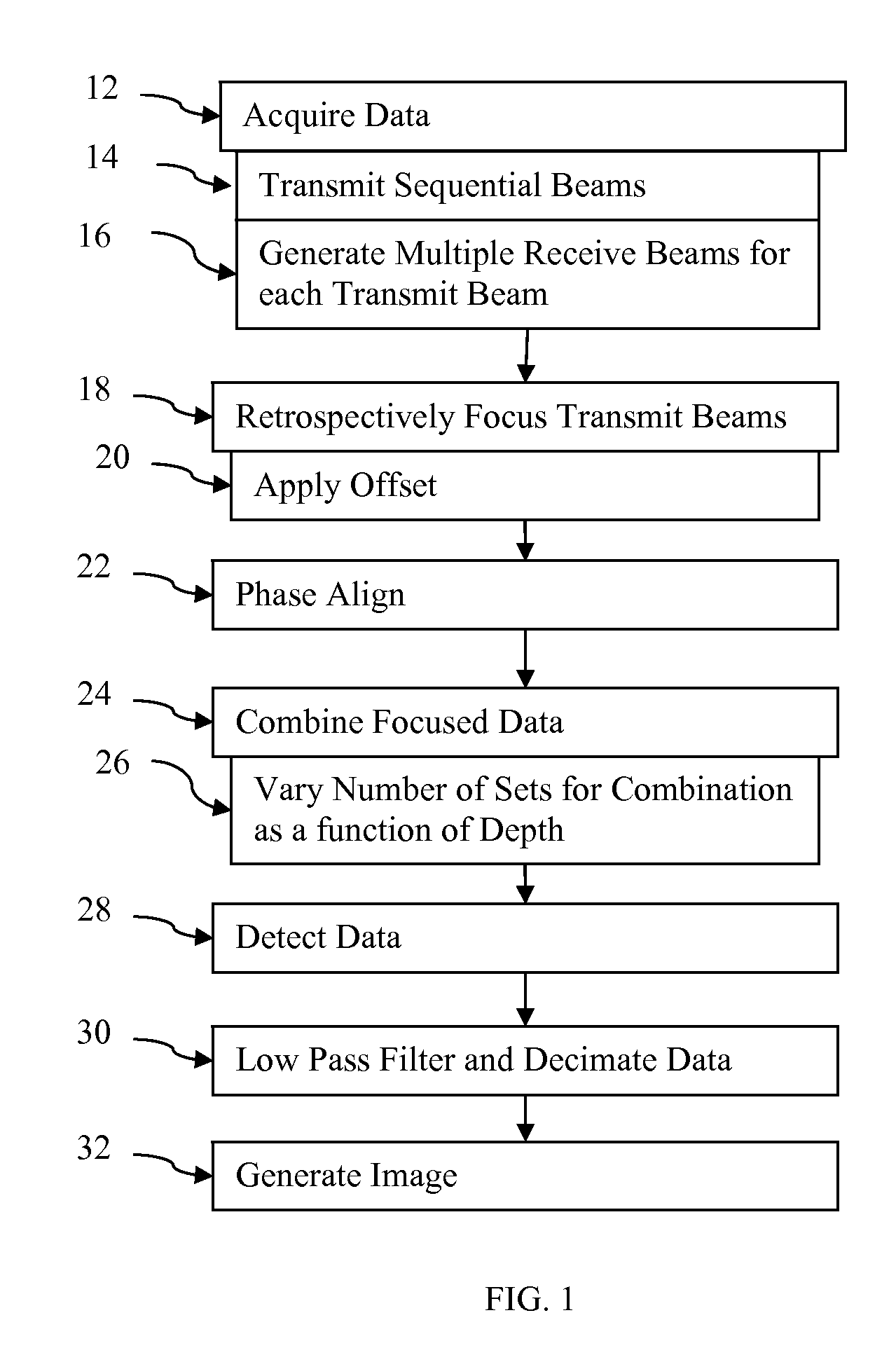
[0021]In retrospective transmit focusing, signals from multiple acquisition events that are in-focus with respect to receive are added pre-detection (synthesized) to reconstruct the signal that would have been received if acquired with a focused transmit at each. One way to achieve retrospective transmit focusing is to transmit with each element of the array in turn while receiving along the same ultrasound line or lines for each acquisition. Next, for each receive focus position and array element, the appropriate focusing delay is applied prior to summing the many signals. However, the number of transmit events required to sample the entire aperture is great, which may not be rapid enough, may have insufficient field strength for harmonic imaging, and may be susceptible to motion artifact.

[0022]In much the same way that there are many basis functions that can be used to decompose a signal (e.g. delta function for standard digitization, sinusoids for Fourier decomposition, etc.), th...


PUM


Abstract

Retrospective dynamic transmit beamformation is provided in medical ultrasound imaging. Using parallel receive beamformation, sets of data representing locations in at least a common field of view are obtained, each set in response to a transmit with a spatially distinct phase front. The common field of view receive data are time aligned and amplitude weighted for retrospective transmit focusing and retrospective transmit apodization, respectively. A time offset, such as of a cycle or more in some cases, is applied to the receive data for retrospective transmit focusing. The offset is selected to emulate shifting the transmit delay profile to be tangentially intersecting with the dynamic receive delay profile for each location which is the desired transmit delay profile. A weight is applied to the receive data for retrospective transmit apodization. The weight is selected based on the desired transmit apodization profile. The offset and weighted data representing a same location from different transmit events is coherently combined. The number of sets of data offset, weighted and combined may vary as a function of depth for dynamic transmit beamformation.

Description

CROSS-REFERENCE TO RELATED APPLICATIONS[0001]The present patent document claims the benefit of the filing date under 35 U.S.C. §119(e) of Provisional U.S. Patent Application Ser. No. 61 / 059,668, filed Jun. 6, 2008, which is hereby incorporated by reference.BACKGROUND[0002]The present patent document relates to coherent combination of received ultrasound signals. In particular, coherent combination of receive data is provided for retrospective dynamic transmit beamformation.[0003]Conventionally to generate a two-dimensional image, acoustic energy is transmitted along a plurality of scan lines sequentially. The transmit beam is focused at one location along the scan line. In response to each transmission, echo signals are received along the respective scan line. The receive beam is dynamically focused as a function of depth (time) along the scan line. Transmit focus is static, and receive focus is dynamic.[0004]For more rapid acquisition, particularly for three-dimensional imaging, a ...

Claims


Application Information

Patent Timeline
IPC IPC(8): A61B8/14
CPCG01S7/52046G01S7/5209G01S7/5202G10K11/346G01S7/52095
Inventor LOFTMAN, RICKARD C.USTUNER, KUTAY F.BRADLEY, CHARLES E.
Owner SIEMENS MEDICAL SOLUTIONS USA INC
Why Eureka
Try Eureka