Hand Protection Structure

a technology for protecting structures and hands, applied in the direction of gloves, protective garments, garments, etc., can solve the problems of accidental injury of hands, user's unconsciously put at risk of being gradually injured by external impact, etc., to reduce the injury caused by external impact, relieve external impact, and improve elasticity

Inactive Publication Date: 2009-12-17
PHILLA INDS
View PDF26 Cites 31 Cited by
  • Summary
  • Abstract
  • Description
  • Claims
  • Application Information

AI Technical Summary

Benefits of technology

[0006]A primary objective of the present invention is to provide a hand protection structure assembled in a glove, adapted for providing a buffer to reduce the injury caused by an external impact.
[0008]The hand protection structure can be assembled in a glove. When the hand is impacted by external forces, the finger protection units relieve the external forces, in which the finger protection units bend toward a reverse bending direction of the fingers by the elasticity of the relief portions until all remained space of the assembling slots are completely filled and the backbone members are compactly combined. Meanwhile, each two adjacent backbone members are also compactly combined against each other for maintaining the shape of the finger protection units, which restricts the finger from further bending toward the reverse bending direction, thus relieving the external impact and providing protection to the fingers.

Problems solved by technology

When working or doing exercises, the hand may be accidentally injured by an external impact, especially, finger fractures or strains caused by reverse bending of the fingers.
However, such a conventional hand protection member 101 of the glove 10 is usually made of soft materials such as plastic and rubber, which may be caused with elasticity fatigue after a long time use, so that the user is unconsciously put at risk of being gradually injured by the external impact.

Method used


Image

  • Hand Protection Structure
  • Hand Protection Structure
  • Hand Protection Structure

Examples


first embodiment

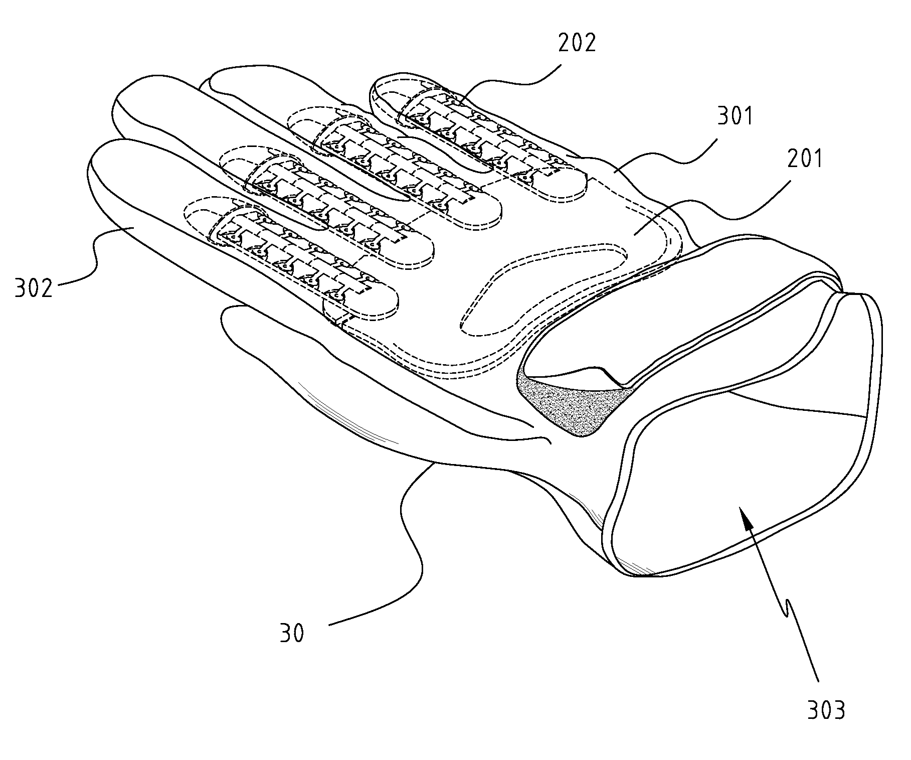
[0020]FIG. 4 is a schematic view illustrating the hand protection structure in accordance with the present invention. Referring to FIG. 4, the hand protection structure 20 is adapted to be assembled in a glove 30. The fixing unit 201 of the hand protection structure 20 is assembled in a palm portion 301 of the glove 30. A plurality of finger portions 302, i.e., forefinger, middle finger, ring finger, etc., extend from an end of the palm portion 301. Each of the finger portions 302 is assembled with one finger protection unit 202 therein. An opening portion 303 is configured at the other end of the palm portion 301. The opening portion 303 is preferably to be provided with a Velcro or an elastic fastening buckle member for adjusting a width of the opening portion 303 according a size of user's wrist. By wearing such a glove 30, the fingers of the user can be instantly protected by elastic support of the finger protection units 202 when the hand of the user is impacted by an external ...

second embodiment

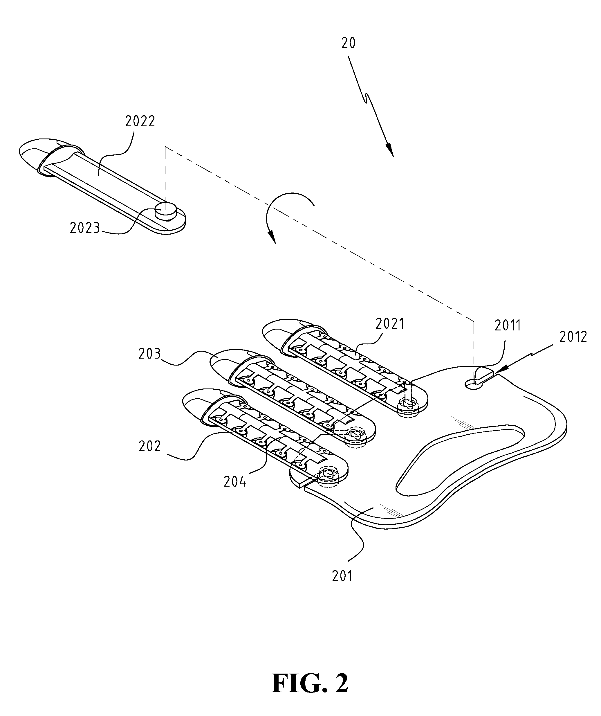
[0023]FIG. 7 is a perspective view of a hand protection structure in accordance with the present invention. Referring to FIG. 7, a joint 2041 is further configured between each two adjacent backbone members 204. The jointing 2041 is configured with a cutting groove at a center surface thereof for allowing the two backbone members 204 to close toward or apart from each other. The joint 2041 is positioned relatively higher than other area of the backbone 204 and is protruded from a surface of the backbone members 204. The joint point 2041 is configured corresponding to a fixing slot 2026 at a surface of the finger protection unit 202 between each two adjacent relief portions 2025. When the backbone members 204 are assembled to the finger protection units 202, the joints 2041 are disposed in the fixing slots 2026 for improving a stability of the backbone members 204 relative to the finger protection units 202. By employing such a relationship between the joints 2041 and the fixing slot...


PUM


Abstract

A hand protection structure is provided. The hand protection structure includes a fixing unit, a plurality of finger protection units, a plurality of fingertip members, and a plurality of backbone members. The finger protection units are configured of flat strip shapes. Each of finger protection units has one fingertip member assembled at a distal end thereof, and a fastening piece is configured at the end thereof of the finger protection unit for mounting the finger protection unit to the fixing unit. The hand protection structure can be assembled in a glove. When a hand of the user is impacted by external forces, the finger protection units relieve the external impact to protect the fingers from injury.

Description

BACKGROUND OF THE INVENTION[0001]1. Field of the Invention[0002]The present invention relates generally to a hand protection structure, and more particularly, to a hand protection structure adapted to be assembled in a glove for providing a buffer to user's hands and protecting the hands from being injured by external impact or press.[0003]2. The Prior Arts[0004]FIG. 1 illustrates a glove having a conventional hand protection structure. As shown in FIG. 1, a glove 10 includes a palm portion and several finger portions, i.e., thumb, forefinger, middle finger, ring finger, and little finger, which extend from an end edge of the palm portion. An opening portion is configured at the opposite end edge of the palm portion, for allowing a user to put in his hand. A non-skid layer (not shown in the drawing) is provided at a front side of the glove. A hand protection member 101 is assembled inside the glove 10. The hand protection member 101 has a certain elasticity, and is configured to ext...

Claims


Application Information

Patent Timeline
Patent Type & Authority Applications(United States)
IPC IPC(8): A41D19/015A41D19/00A41D13/08
CPCA41D19/01588A63B2243/0025A63B71/148
Inventor CHANG, BRUCE
Owner PHILLA INDS
Why Eureka
Try Eureka