
Methods and systems for managing facility power and cooling

a technology for managing facilities and power, applied in the field of method and system management of facility power, can solve the problems of affecting the power supply of an entire rack of servers, affecting the accuracy of manual load distribution between multiple phases, and affecting the power supply of emergency power supply arrangements

Active Publication Date: 2009-12-17
SCHNEIDER ELECTRIC IT CORP
View PDF40 Cites 95 Cited by
  • Summary
  • Abstract
  • Description
  • Claims
  • Application Information

AI Technical Summary

Benefits of technology

[0009]In the past, when replacing equipment or adding new equipment, data center managers may have simply employed a trial and error methodology by manually plugging in a server, turning it on, and seeing if the circuit breaker trips due to an overload, with an unfortunate result of loss of power to an entire rack of servers. Alternatively, they may have connected equipment after evaluating the current load at the power supply. This approach also exposes the system to a potent

Problems solved by technology

However, the complexity of the distribution system and the fact that the load varies over time makes it difficult for individuals to manually distribute the load accurately between multiple phases.
Overloading a phase of a power supply, such as a power distribution unit (PDU) or uninterruptible power supply (UPS), can lead to loss of the secure power from the power supply or cause breakers to trip, thereby dropping the load.
In the past, when replacing equipment or adding new equipment, data center managers may have simply employed a trial and error methodology by manually plugging in a server, turning it on, and seeing if the circuit breaker trips due to an overload, with an unfortunate result of loss of power to an entire rack of servers.
This approach also exposes the system to a potential loss of power to an entire rack if the data equipment connected to the power supply scale up in power consumption over time.
Other approaches include relying on the equipment manufacturers' reported calculated power consumption data or specifications and assuming even distribution of the power load between phases on a power supply, or dramatically oversizing the distribution and power systems to reduce the effect phase balancing may be imprecise, inefficient, and expensive.

Method used


Image

  • Methods and systems for managing facility power and cooling
  • Methods and systems for managing facility power and cooling
  • Methods and systems for managing facility power and cooling

Examples


Embodiment Construction

[0026]This invention is not limited in its application to the details of construction and the arrangement of components set forth in the following description or illustrated in the drawings. The invention is capable of other embodiments and of being practiced or of being carried out in various ways. Also, the phraseology and terminology used herein is for the purpose of description and should not be regarded as limiting. The use of “including,”“comprising,” or “having,”“containing,”“involving,” and variations thereof herein, is meant to encompass the items listed thereafter and equivalents thereof as well as additional items.

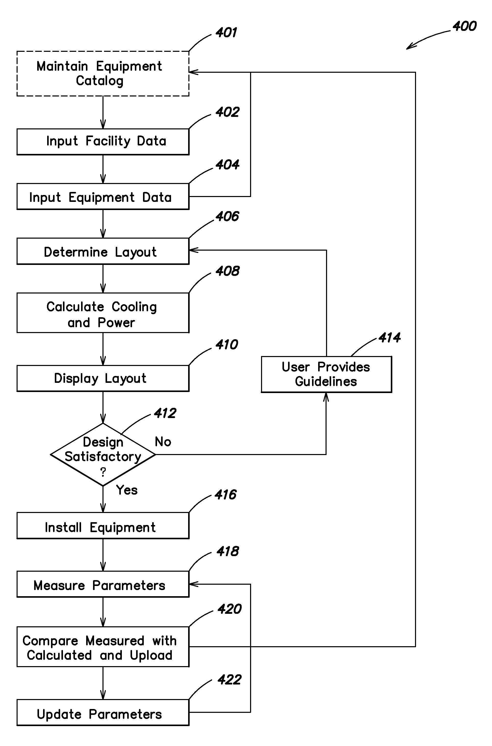
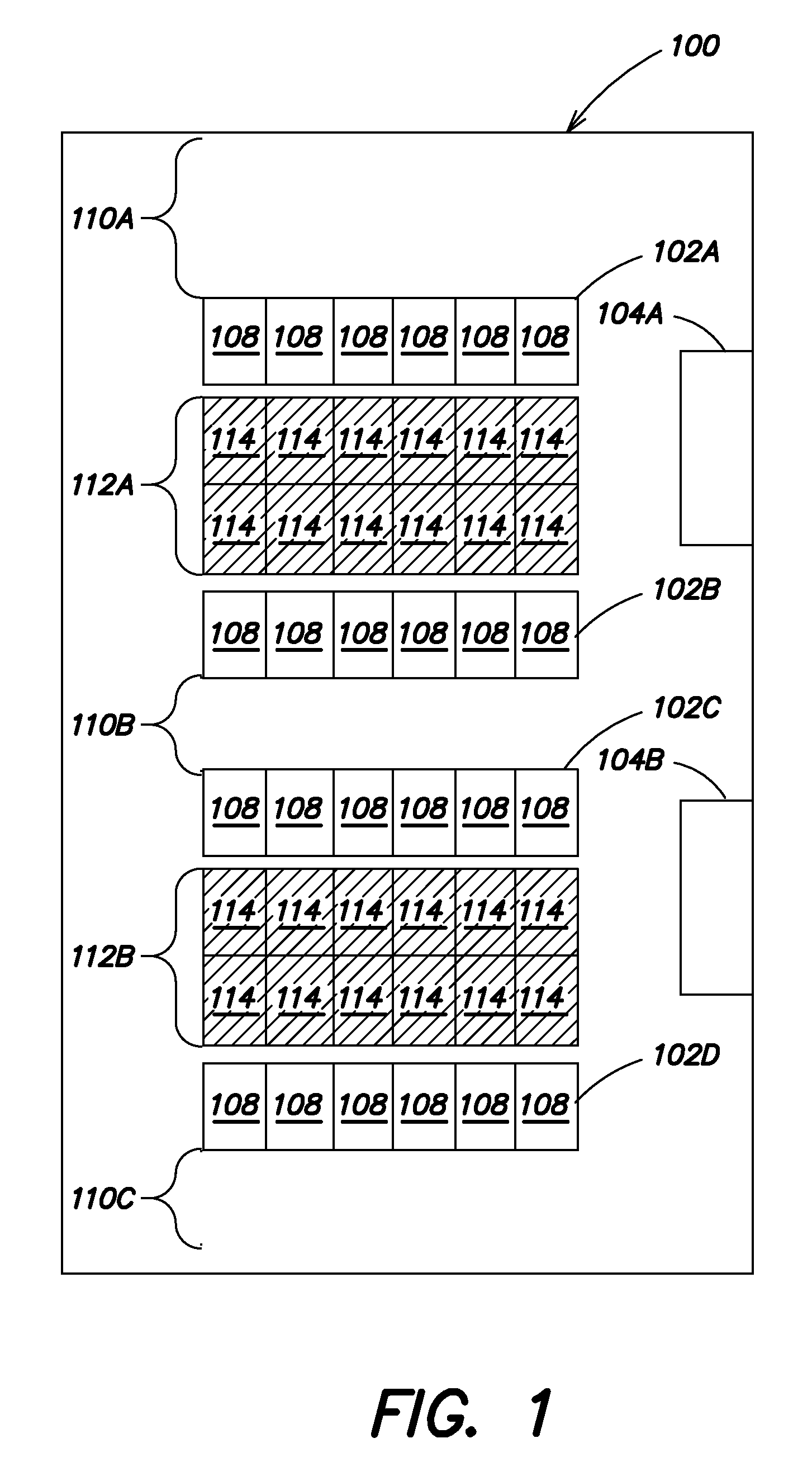
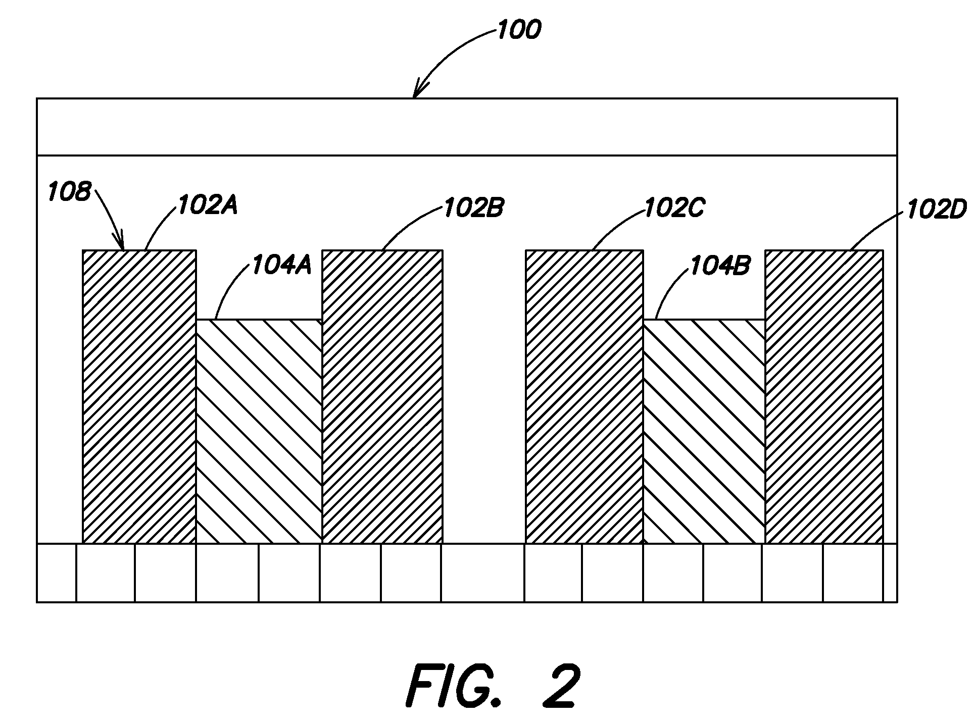
[0027]Embodiments of the present invention may be used to design, manage and retrofit a data center, such as data center 100 which is shown in FIGS. 1 and 2 with FIG. 1 showing a top view of the data center 100, and FIG. 2 showing a side view of the data center 100. As discussed further below, the design of the layout of the data center 100, including various da...


PUM

PropertyMeasurementUnit
Poweraaaaaaaaaa
Cooling capacity (W)aaaaaaaaaa

Abstract

A method and corresponding apparatus provide a determination of available power capacity of a phase of a power supply in a data center rack. The method includes metering the power of a power supply and calculating an average peak power draw per phase of the power supply. Using average peak power draw per phase of the power supply and the expected power draw data corresponding to data center equipment coupled to the power supply, the available power capacity can be calculated on a per phase of the power supply. A method and corresponding apparatus for managing data center equipment may use the phase based available power capacity calculations to determine the optimal placement of new data center equipment within a data center configuration.

Description

BACKGROUND OF INVENTION[0001]1. Field of Invention[0002]Embodiments of the invention relate generally to entity management, and more specifically to methods and systems for managing facility power.[0003]2. Discussion of Related Art[0004]Centralized data centers for computer, communications and other electronic equipment have been in use for a number of years, and more recently with the increasing use of the Internet, large scale data centers that provide hosting services for Internet Service Providers (ISPs), Application Service Providers (ASPs) and Internet content providers are becoming more prevalent. Typical centralized data centers contain numerous racks of equipment that require power, cooling and connections to external communications facilities. In modern data centers and network rooms, the increased density of computing equipment used in these facilities has put strains on the cooling and power systems of the facilities. In the past, typical power consumption for each equip...

Claims


Application Information

Patent Timeline
IPC IPC(8): G05B21/02G01R21/00
CPCH02J3/00G06F1/26
Inventor LEHMANN, GERTDALGAS, MIKKELHARMS, FLEMMING NICOLAS
Owner SCHNEIDER ELECTRIC IT CORP
Learn More