Color Calibration System for a Video Display

a color calibration and video display technology, applied in the field of displays, can solve the problems of insufficient tolerance of leds and their associated drive circuitry to allow their use in uncalibrated displays, prohibitively expensive and time-consuming conventional display calibration techniques utilizing calorimeters and luminance meters

Inactive Publication Date: 2009-12-17
BARCO INC
View PDF7 Cites 20 Cited by
  • Summary
  • Abstract
  • Description
  • Claims
  • Application Information

AI Technical Summary

Problems solved by technology

Light emitting elements, such as LEDs and their associated drive circuitry, are not manufactured to a close enough tolerance to allow their use uncalibrated in such displays.
Although the manufacturers of LEDs sort their production into bins by nominal intensity and color, the tolerance of these bins are not good enough for this demanding application.
Conventional display calibration techniques utilizing calorimeters and luminance meters can be prohibitively expensive and time consuming when applied to a large display having very large numbers of pixels.
However, such techniques do not allow the display to be operated at different color standards without recalibration, nor do they allow for the differences in photopic (day-time) and scotopic (night-time) vision.

Method used


Image

  • Color Calibration System for a Video Display
  • Color Calibration System for a Video Display
  • Color Calibration System for a Video Display

Examples


Embodiment Construction

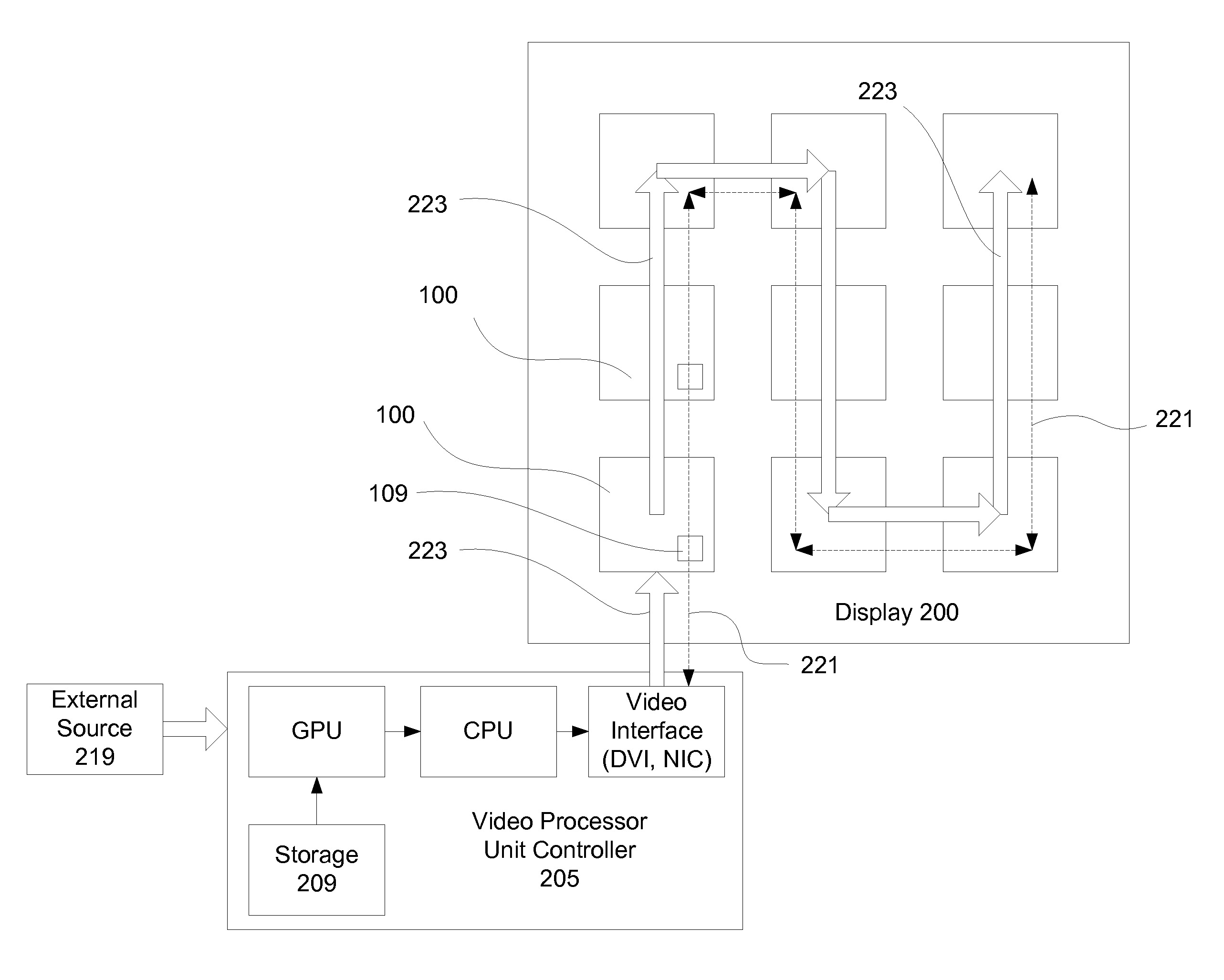
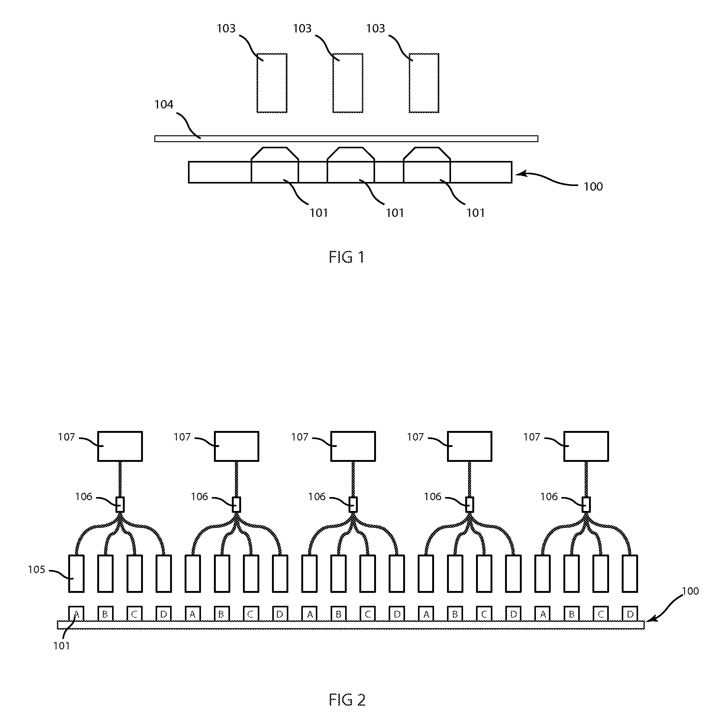
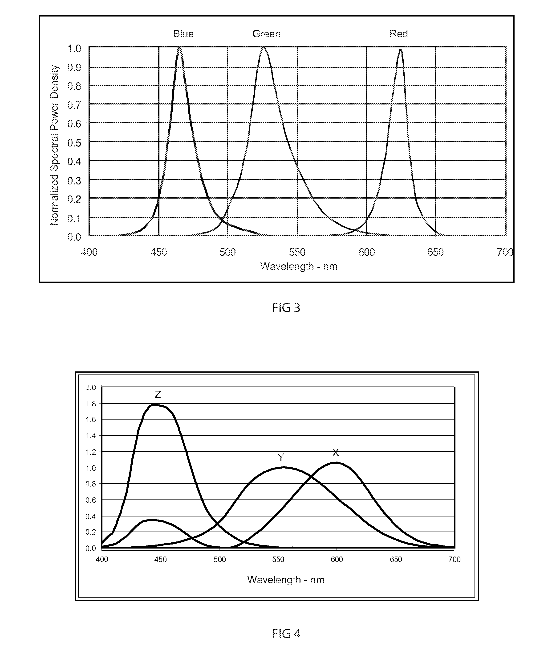
[0016]To calibrate prior art display systems comprising groups of light emitting elements, such as light emitting diodes (LEDs), prior practice has been to store values of the Commission Internationale de L'Eclairage (CIE) chromaticity coordinates (x, y) for photopic vision and luminance for each pixel to calculate transformation matrices for color calibration. However, using the CIE chromaticity coordinates ties the display to a specific color space and standard, thereby precluding any operation with alternate color spaces or in the scotopic vision color space. In other words, the prior art systems use stored values which already include correction factors or coefficients which limited the calibration of the light emitting elements to certain color spaces and standards.

[0017]In contrast, the system disclosed herein stores luminance and chromaticity data for each of the light emitting elements with the display panels to which the elements belong. From the stored normalized power spe...


PUM

PropertyMeasurementUnit
luminanceaaaaaaaaaa
power spectral densityaaaaaaaaaa
relative luminanceaaaaaaaaaa

Abstract

Large digital displays for entertainment, architectural and advertising displays have interconnected display panels with pluralities of light emitting elements. To solve calibration problems, each of the display panels stores measured luminance and chromaticity data for each of the light emitting elements of the panel. The luminance data is independent of the chromaticity data. A central controller can then perform calibration procedures so that the light emitting elements are matched across the entire display.

Description

CROSS-REFERENCE TO RELATED APPLICATIONS[0001]This patent application claims the benefit of U.S. provisional patent applications 61 / 061,338; 61 / 061,347; 61 / 061,353; 61 / 061,358; 61 / 061,365; and 61 / 061,369, all filed Jun. 13, 2008, which are incorporated by reference along with all other references cited in this application.BACKGROUND OF THE INVENTION[0002]This patent generally relates to displays and particularly to large display systems comprising groups of light emitting elements. The invention discloses improvements in the calibration of the light emitting elements.[0003]Large display systems for entertainment, architectural, and advertising purposes have commonly been constructed of numbers of light emitting elements, such as LEDs or incandescent lamps mounted onto flat tiles. The light emitting elements can be selectively turned on and off to create patterns, graphics and video displays for both informational and aesthetic purposes. It is well known to construct these displays as...

Claims


Application Information

Patent Timeline
Patent Type & Authority Applications(United States)
IPC IPC(8): H01J9/42
CPCG06F3/1446Y10T29/49826G01J3/28G09F9/3026F21S2/005F21V21/088G06F1/00G06F3/017G06F3/0304G09F9/33H05K999/99
Inventor ELLIOTT, GRANT ARTHUR JOHN
Owner BARCO INC
Why Eureka
Try Eureka