Sexual stimulation apparatus

a technology of sexual stimulation and a grip, which is applied in the field of sexual stimulation apparatus, can solve the problems of user discomfort, discomfort or pain in wrists, upper arms, shoulder and/or back pain, and is difficult for users to comfortably grip a conventional sexual stimulation apparatus during use, so as to facilitate interdigital engagement and facilitate engagement with said users' fingers

a technology of sexual stimulation and a grip, which is applied in the field of sexual stimulation apparatus, can solve the problems of user discomfort, discomfort or pain in wrists, upper arms, shoulder and/or back pain, and is difficult for users to comfortably grip a conventional sexual stimulation apparatus during use, so as to facilitate interdigital engagement and facilitate engagement with said users' fingers

US20090312599A1Inactive Publication Date: 2009-12-17SMITH SHANNON

Image

  • Sexual stimulation apparatus
  • Sexual stimulation apparatus
  • Sexual stimulation apparatus

Examples


Embodiment Construction

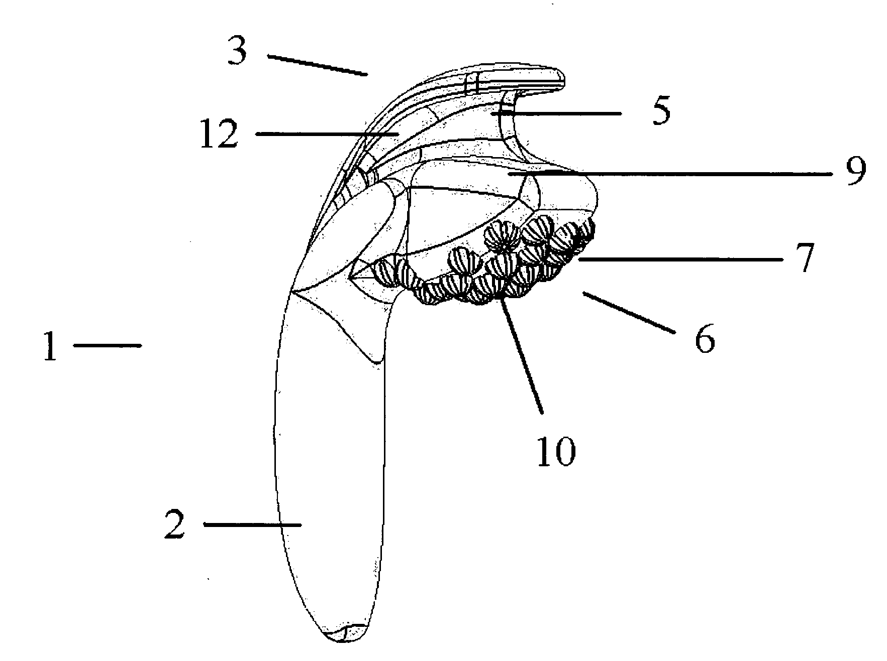
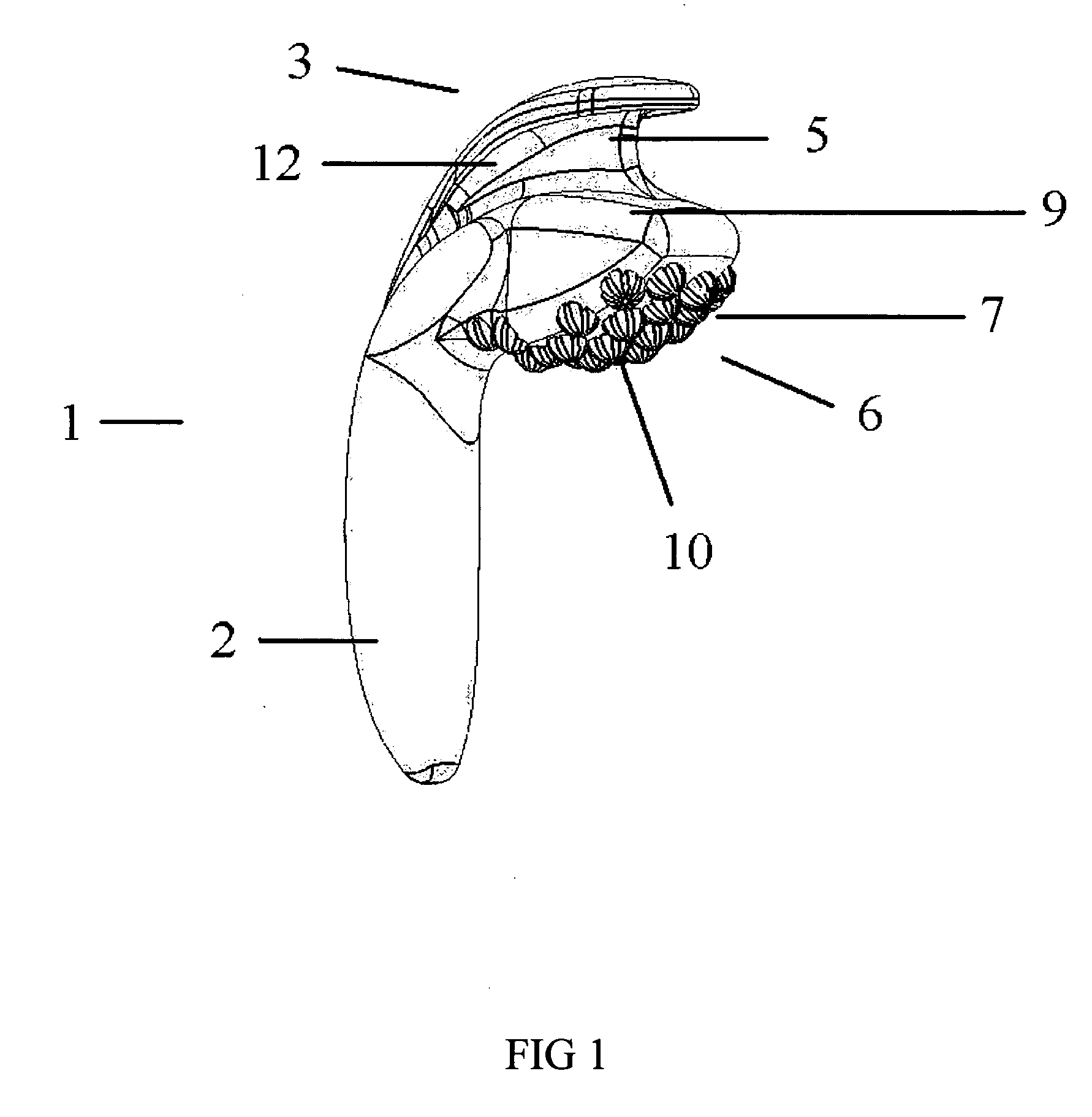
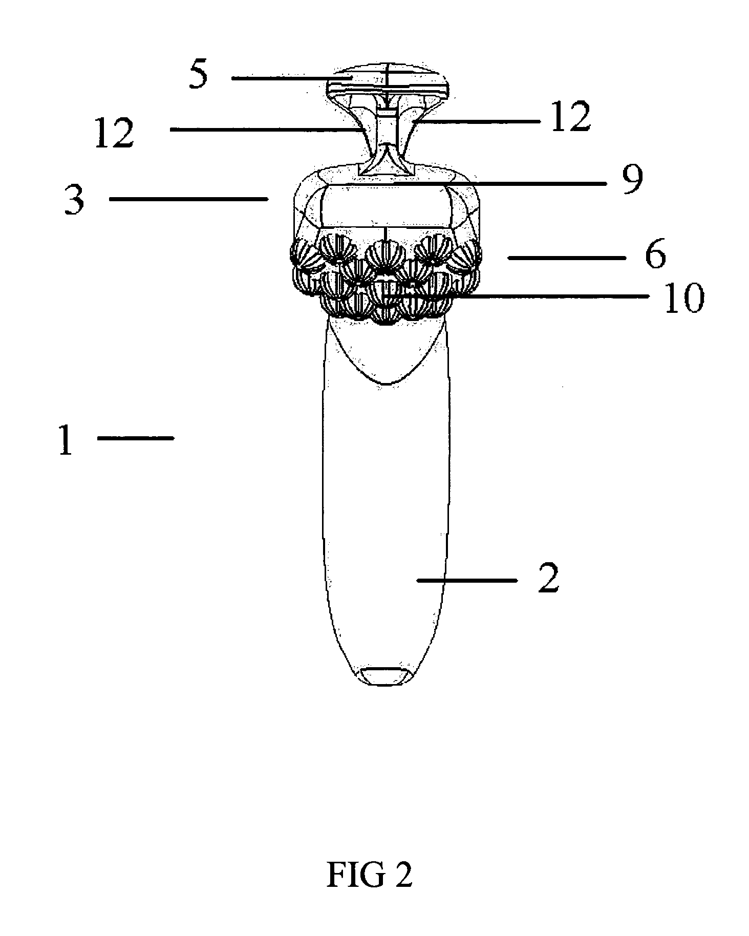
[0035]As shown in FIGS. 1 to 4, the sexual stimulation apparatus 1 of the present invention generally includes a phallic shaped member 2 having a handle 3 disposed at the base thereof. The handle 3 generally includes a projection member 5 and a clitoral stimulator 6.

[0036]As best shown in FIGS. 1 to 3, the handle 3 and the phallic shaped member 2 are integrally formed from silicone. The handle 3 includes a convex surface 9 and a clitoral stimulator 6 is located on the opposing surface. The clitoral stimulator 6 comprises a plurality of spaced apart nodules 10. In use, the spaced apart nodules 10 contact the clitoris of the user 11 thereby increasing the stimulation and pleasure derived from using the sexual stimulation apparatus 1 of the present invention when masturbating. The handle 3 also acts as a definitive end portion of the sexual stimulation apparatus 1 and thereby allows an individual user 11 to fully insert the sexual stimulation apparatus into their vagina until the clito...


PUM


Abstract

A sexual stimulation apparatus comprising a phallic shaped member having a handle disposed at its base. The handle has a convex surface substantially facing away from the phallic shaped member. The convex surface has at least one projection member extending therefrom. In use, the convex surface sits snugly against the palm and fingers of a user's hand, and the projection member interdigitally engages with the user's hand.

Description

TECHNICAL FIELD[0001]The present invention relates to a sexual stimulation apparatus and particularly to a sexual stimulation apparatus designed for use by women to increase their personal comfort when using the sexual stimulation apparatus during masturbation.BACKGROUND ART[0002]Sexual stimulation apparatus are well known and have been commercially available for many decades. Conventional sexual stimulation apparatus include dildos, vibrators and the like and are typically made from plastic, metal, silicone, rubber or other similar materials. Conventional sexual stimulation apparatus have a straight or curved shaft that is typically shaped to resemble a phallus. The shaft typically does not include a handle and at best, the shaft may include a bulbous end to assist in a user gripping the sexual stimulation apparatus during use.[0003]However, because the shaft of a conventional sexual stimulation apparatus does not include a handle, it is difficult for a user to grip a conventional ...

Claims


Application Information

Patent Timeline
17 Dec 2009
Publication
US20090312599A1
IPC
A61F5/00; A61H19/00
CPC
A61H19/34; A61H2201/0153; A61H23/02; A61H19/44
Inventors
SMITH, SHANNON