Safety goggles structure

a safety goggles and structure technology, applied in the field of safety goggles structure, can solve the problems of safety hazards, liquid splashing, and the chance of entering the safety goggles or damaging the eyes of construction workers, and achieve the effects of improving the anti-fog effect, enhancing the heat dissipation effect, and improving the connection stability

Inactive Publication Date: 2009-12-24
T LINK PPE
View PDF4 Cites 70 Cited by
  • Summary
  • Abstract
  • Description
  • Claims
  • Application Information

AI Technical Summary

Benefits of technology

[0012]With the aforementioned design of various latch structures, the present invention achieves the effect of securely connecting the frame and the lens when the goggles structure is in use, so as to improve the connecting stability.
[0013]With the upper guide channel slantingly and concavely disposed at the top of the front side of the frame and upwardly tapered and the lower guide channel disposed at the bottom of the front side of the frame and upwardly tapered, air enters from the bottom and discharges from the top when the safety goggles structure of the invention is in use, so as to achieve the effect of distributing gases. In other words, the lens will not produce fogs. With the slanting design, foreign substances such as dusts, pebbles and liquid splashes will not enter into the safety goggles easily or damage the eyes of workers. The upper guide channel and the lower guide channel come with an upwardly tapered design. From conservation of mass, if air flows from a large cross-sectional area to a small cross-secti

Problems solved by technology

In addition, fogs are easily produced on the lenses of the goggles in the situation when the temperature changes or when the workers inhale and exhale, and thus causing a safety issue during construction.
To overcome the issue of having fogs on the lenses, the present safety goggles come with the design of air holes, but the air holes constitute a leak of the safety goggles, and the foreign matters such as

Method used


Image

  • Safety goggles structure
  • Safety goggles structure
  • Safety goggles structure

Examples


Embodiment Construction

[0026]The above and other objects, features and advantages of the present invention will become apparent from the following detailed description taken with the accompanying drawings.

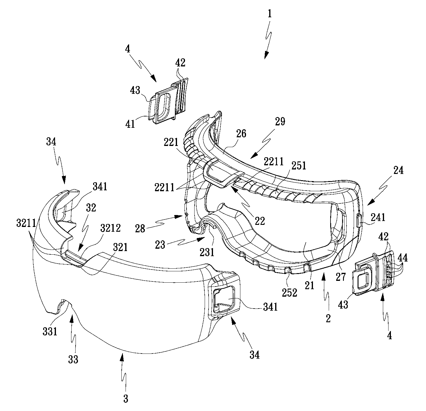
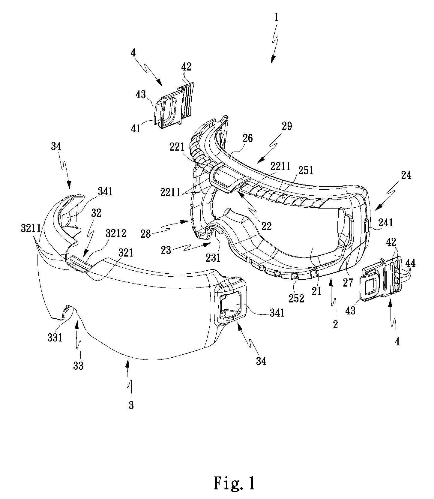
[0027]Referring to FIG. 1 for an exploded view of a preferred embodiment of the present invention, a safety goggles structure 1 of the invention comprises a frame 2, a lens 3 and two elastic buckles 4.

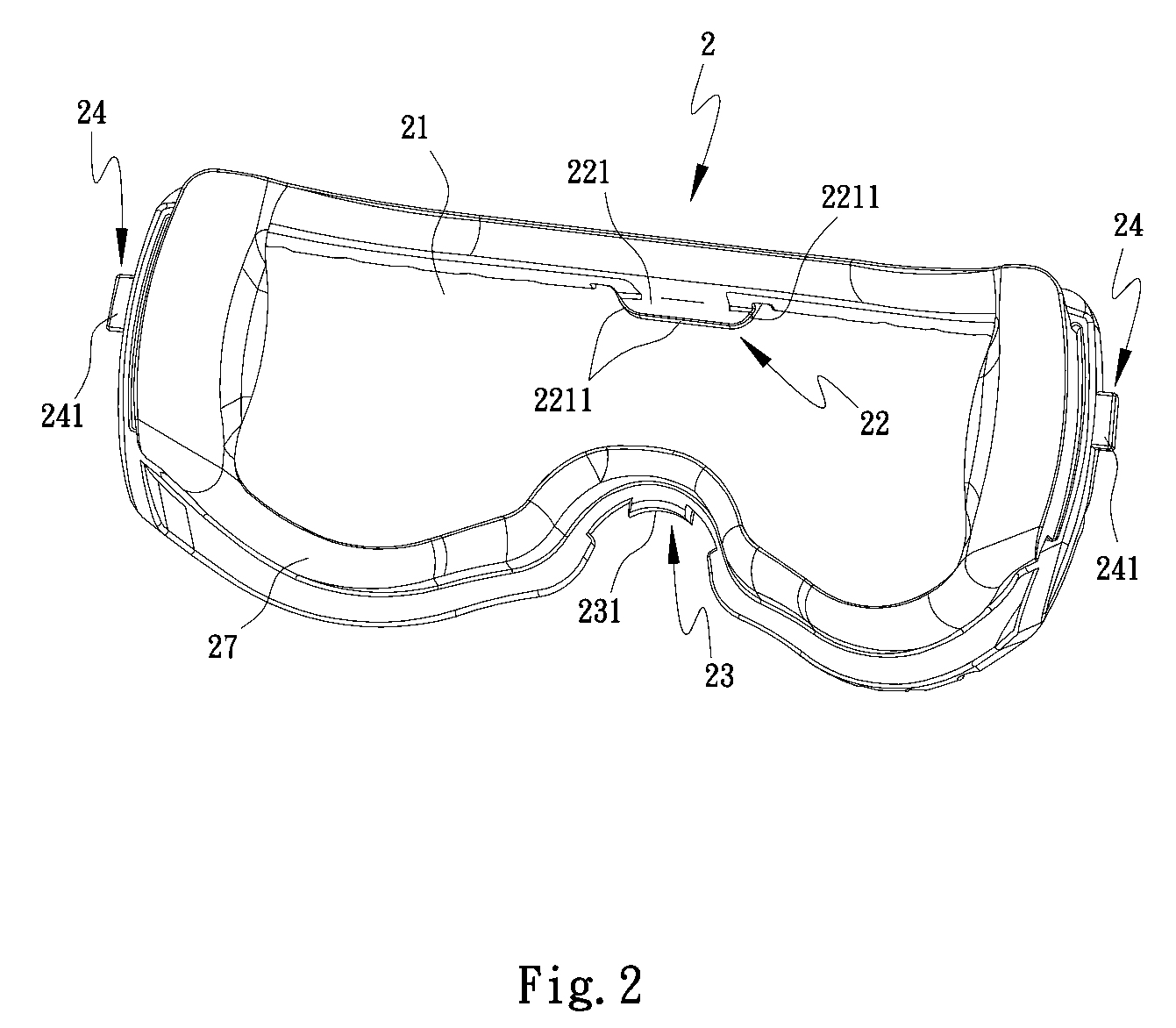
[0028]With reference to FIGS. 1 and 2, FIG. 2 shows a perspective view of a frame in accordance with a preferred embodiment of the invention from another viewpoint, the frame 2 is substantially in a ring-shape and has an opening 21 around the frame 2, and the frame 2 includes a frame connecting portion 22, a frame latch portion 23, two frame snap-in portions 24, at least one upper guide channel 251, at least one lower guide channel 252 and an upper gutter 26. The frame connecting portion 22 is disposed at the top of the frame 2, and the frame latch portion 23 is disposed at the bottom of the frame 2, and tw...


PUM


Abstract

The present invention discloses a safety goggles structure having a frame connecting portion, a frame latch portion, two frame snap-in portions, a lens connecting portion, a lens latch portion, two lens snap-in portions and two elastic buckles to mount a lens onto a frame for achieving the effect of securely connecting the frame and the lens or improving their connecting stability. With an upper guide channel slantingly and concavely disposed on the frame and a lower guide channel vertically up-and-down and concavely disposed on the frame, gases and liquids can pass through without producing fogs and accumulating liquid on the lens, and foreign substances cannot enter into the safety goggles easily to cause any safety issue. With the design of an upper gutter on the frame, liquid splashed onto the safety goggles can flow along either side of the upper gutter to prevent liquid accumulation or leaking.

Description

FIELD OF THE INVENTION[0001]The present invention relates to a safety goggles structure, and more particularly to a safety goggles structure capable of improving the connecting stability and preventing fogs and liquid accumulations or leaks.BACKGROUND OF THE INVENTION[0002]At a general construction site, workers usually wear a pair of goggles to protect their eyes from foreign matters such as dusts, pebbles and liquid splashes produced during constructions.[0003]Traditional goggles are nothing more than a structure composed of a frame and lenses latched and connected with each other, but the design of the latch and connected structure is very simple, and thus the frame and the lenses may be easily separated from each other when the goggles are worn or removed.[0004]In addition, fogs are easily produced on the lenses of the goggles in the situation when the temperature changes or when the workers inhale and exhale, and thus causing a safety issue during construction. To overcome the ...

Claims


Application Information

Patent Timeline
IPC IPC(8): A61F9/02
CPCA61F9/025
Inventor WANG, MING-CHUN
Owner T LINK PPE
Why Eureka
Try Eureka