Method and device for managing cryptographic keys in secret communications network

a cryptographic key and communication network technology, applied in the field of secret communications networks, can solve the problems of cryptanalysis requiring a large amount of calculation, cryptographic key consumption, and cryptographic key consumption, and achieve the effect of managing easily and stably

Active Publication Date: 2009-12-24
NEC CORP
View PDF2 Cites 50 Cited by
  • Summary
  • Abstract
  • Description
  • Claims
  • Application Information

AI Technical Summary

Benefits of technology

[0018]According to the present invention, key generation control on a first node is performed based on the amounts of stored cryptographic keys (stored key amounts) of individual second nodes, stored at the first node, whereby cryptographic keys of the multiple nodes can be managed easily and stably.

Problems solved by technology

The Internet is an economic and social infrastructure over which various kinds of data are exchanged, and therefore it is an important issue to provide for preventive measures to protect the data flowing over the network beforehand from risks of eavesdropping.
This method is used to distribute a cryptographic key for common key cryptography because it is not suitable for high-speed processing.
Security according to these methods depends on the fact that an enormous amount of calculation is required for cryptanalysis.
However, conventional technologies place importance on cryptographic key generation, and cryptographic key management has hardly been performed with consideration given to the fact that a cryptographic key is also consumed.
In addition, generally, key generation rates at which cryptographic keys are generated through the key generation and sharing process are not uniform among nodes because the key generation rate depends also on the distance between nodes and the quality of communication.
The management of cryptographic keys becomes more complicated as the number of nodes increases.
Accordingly, encrypted communication cannot be performed between remote nodes.
However, encrypted communication cannot be performed between nodes which have never performed key generation and sharing process because no cryptographic key is shared between these nodes.

Method used


Image

  • Method and device for managing cryptographic keys in secret communications network
  • Method and device for managing cryptographic keys in secret communications network
  • Method and device for managing cryptographic keys in secret communications network

Examples


first exemplary embodiment

1. First Exemplary Embodiment

1.1) Network Structure

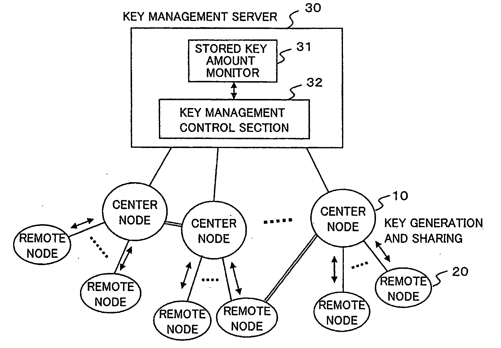
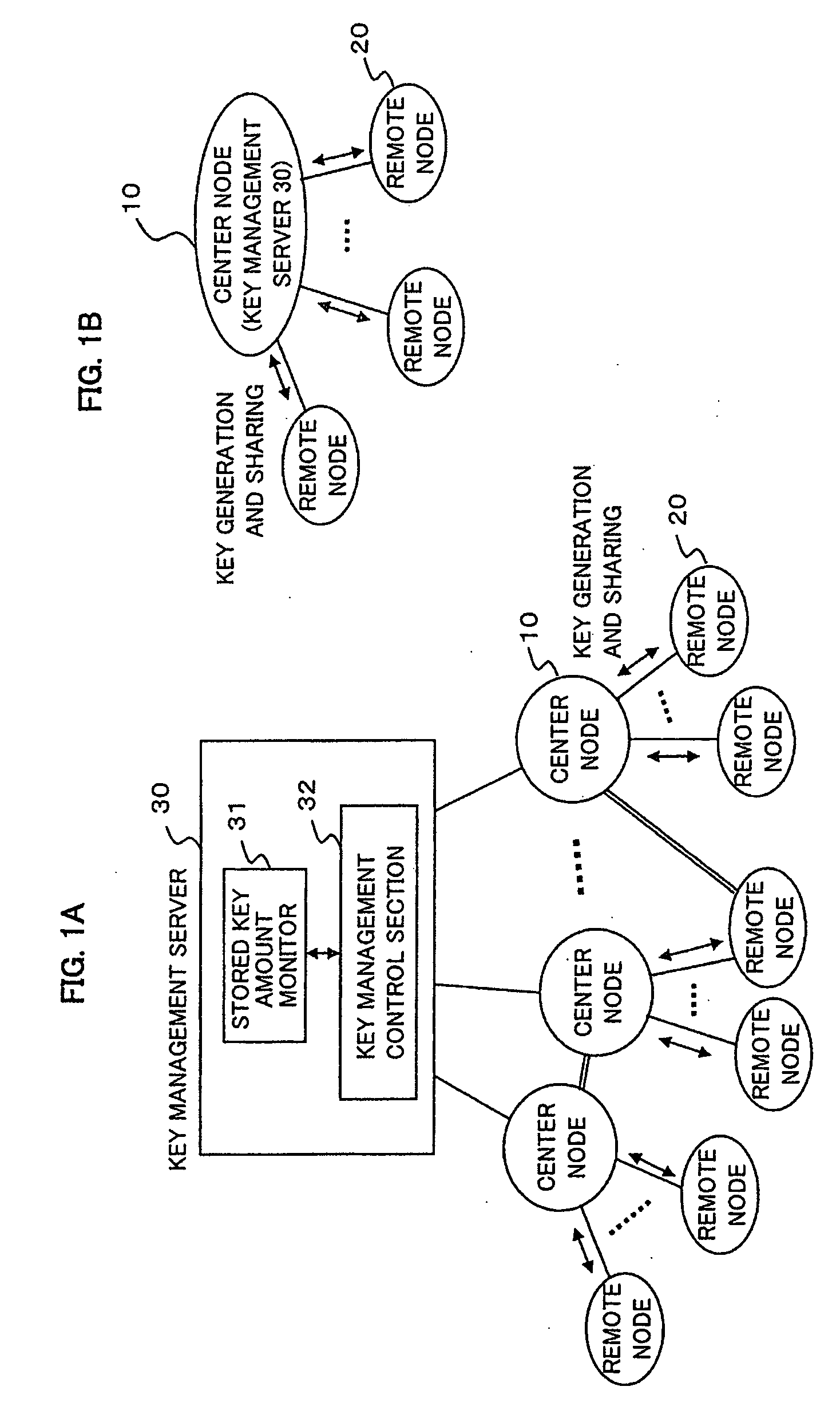
[0033]FIGS. 1A and 1B are schematic diagrams respectively showing two examples of a secret communications network to which a cryptographic key management system according to a first exemplary embodiment of the present invention is applied. Here, to avoid complicated description, it is assumed that the secret communications network shown in FIG. 1A includes a plurality of center nodes 10, a plurality of remote nodes 20, and a key management server 30, and that each of the center nodes 10 is connected to some of the remote nodes 20 and is connected to the key management server 30. Moreover, it is assumed that some connections between center nodes 10, between a center node 10 and a remote node 20, and / or between remote nodes 20 are made securely through closed paths, as indicated as an example by double lines in FIG. 1A, and that these entities in their entirety constitute a single network.

[0034]Additionally, each of the center nodes 1...

second exemplary embodiment

2. Second Exemplary Embodiment

2.1) Structure and Configuration

[0044]FIG. 3 is a block diagram showing the schematic structures and configurations of a center node and remote nodes in a secret communications network according to a second exemplary embodiment of the present invention. Here, it is assumed that N (multiple) remote nodes 20 (hereinafter, referred to as remote nodes RN-1 to RN-N) are each connected to a center node 10 through optical fiber, and that cryptographic key generation and sharing, as well as encrypted communication using a cryptographic key, are performed between each remote node and the center node 10.

[0045]Each of the remote nodes RN-1 to RN-N has a similar configuration and includes a quantum channel unit 201, a classical channel unit 202, a control section 203 for controlling these units, a quantum key memory 204 for storing quantum key information, and a remote key memory 205 for storing a cryptographic key for communication between remote nodes.

[0046]The r...

third exemplary embodiment

3. Third Exemplary Embodiment

3.1) Structure

[0080]FIG. 7 is a block diagram showing the schematic structures of center nodes and remote nodes in a secret communications network according to a third exemplary embodiment of the present invention. In the present exemplary embodiment, description will be given of a case where a remote key is shared between remote nodes belonging to different center nodes in a N:M connection network.

[0081]First, in a QKD network A (QKD-NW-A), each of N remote nodes RN-A1 to RN-AN is connected to a center node 10a thorough optical fiber, constituting a 1:N network. In a QKD network B (QKD-NW-B), each of M remote nodes RN-B1 to RN-BM is connected to a center node 10b through optical fiber, constituting a 1:M network.

[0082]Each remote node and the center node in each QKD network perform a cryptographic key generation process, a cryptographic key sharing process, and encrypted communication using a cryptographic key as described above. The configuration of ea...


PUM


Abstract

A cryptographic key management method and device are provided by which cryptographic keys of multiple nodes can be managed easily and stably. A system includes at least one first node and a plurality of second nodes connected to the first node, and the first node individually generates and consumes a cryptographic key with each of the second nodes connected to the first node itself. A cryptographic key management device in such a system has a monitor that monitors the stored key amounts of cryptographic keys of the individual second nodes, stored at the first node, and a key management control section that performs key generation control on the first node, based on the stored key amounts.

Description

BACKGROUND OF THE INVENTION[0001]1. Field of the Invention[0002]This application is based upon and claims the benefit of priority from Japanese Patent Application No. 2007-153807, filed on Jun. 11, 2007, the disclosure of which is incorporated herein in its entirety by reference.[0003]The present invention relates to a secret communications network and, more particularly, to a method and device for managing cryptographic keys to be used between nodes.[0004]2. Description of the Related Art[0005]The Internet is an economic and social infrastructure over which various kinds of data are exchanged, and therefore it is an important issue to provide for preventive measures to protect the data flowing over the network beforehand from risks of eavesdropping. A secret communications system, in which data for communication is encrypted, can be cited as one of the preventive measures. There are two broad types of cryptographic methods: common key cryptography and public key cryptography.[0006]...

Claims


Application Information

Patent Timeline
Patent Type & Authority Applications(United States)
IPC IPC(8): H04L9/08H04L9/14H04L9/12
CPCH04L9/0855H04L9/0891H04L9/083
Inventor MAEDA, WAKAKOTAJIMA, AKIOTANAKA, AKIHIROTAKAHASHI, SEIGO
Owner NEC CORP
Why Eureka
Try Eureka