

Applicators that house and support ultrasound transducers for transcutaneou delivery of ultrasound energy
- Summary
- Abstract
- Description
- Claims
- Application Information
AI Technical Summary
Benefits of technology
Problems solved by technology
Method used
Image

Examples
Embodiment Construction
[0023]The various aspects of the invention will be described in connection with the therapeutic indication of providing increased blood perfusion by the transcutaneous application of ultrasonic energy. That is because the features and advantages of the invention are well suited to this therapeutic indication. Still, it should be appreciated that many aspects of the invention can be applied to achieve other diagnostic or therapeutic objectives as well.
[0024]Furthermore, in describing the various aspects of the invention in the context of the illustrated embodiment, the region targeted for an increase in blood perfusion is the thoracic cavity (i.e., the space where the heart and lungs are contained). It should be appreciated, however, that the features of invention have application in other regions of the body, too, for example, in the arms, legs, or brain.
I. System for Providing Noninvasive Ultrasound-Assisted Blood Perfusion
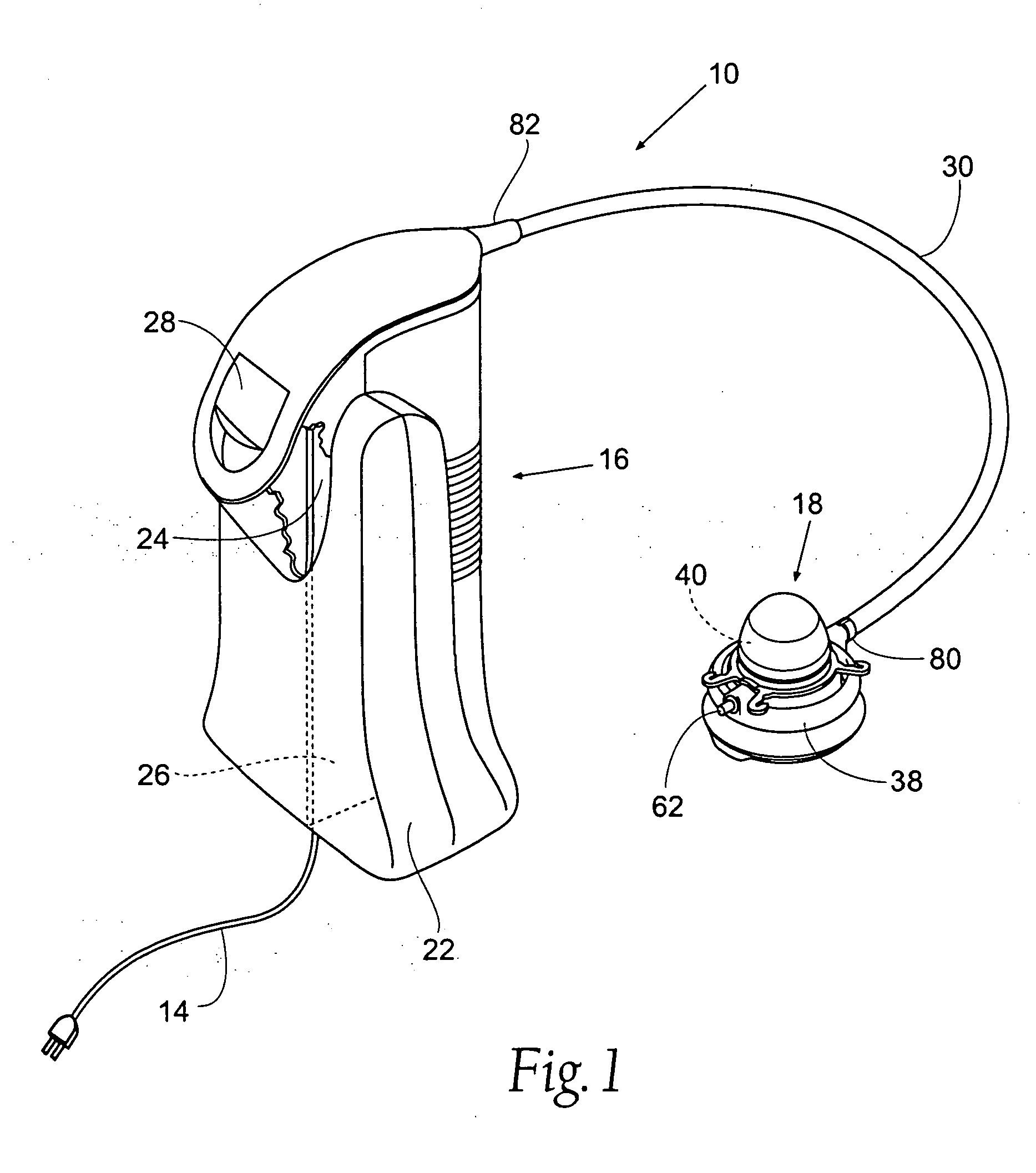
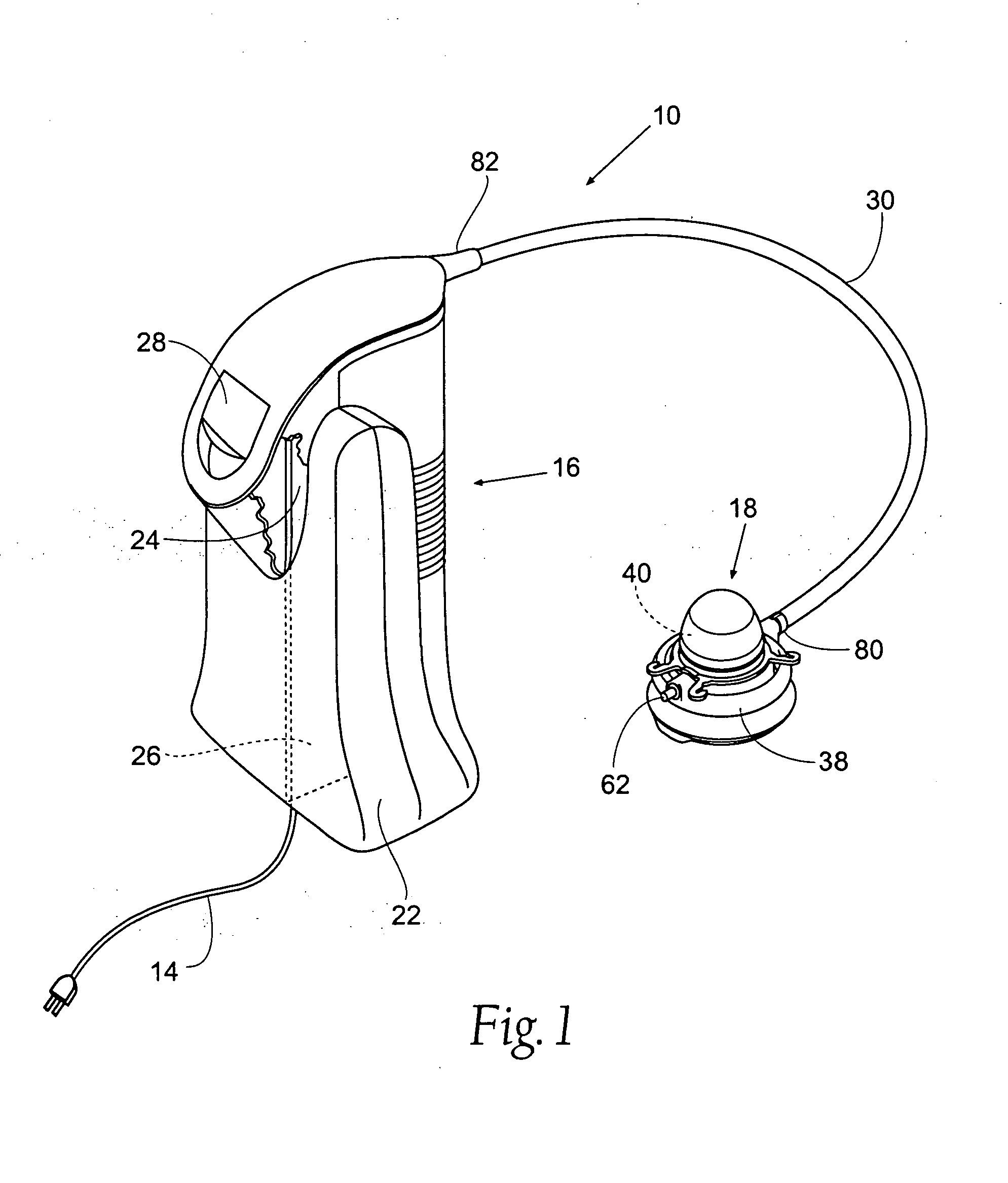
[0025]FIG. 1 schematically shows a compact, portable therap...
PUM
 Abstract
Description
Claims
Application Information