Puncturing needle assisting tool
- Summary
- Abstract
- Description
- Claims
- Application Information
AI Technical Summary
Problems solved by technology
Method used
Image

Examples
first embodiment
[0083]In regards to the action of the first embodiment, an explanation will be given regarding a case wherein the puncturing needle assisting tool 110 is used to suture together the abdominal wall A and the gastric wall B.
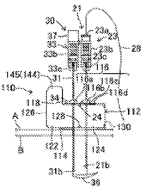
[0084]First, as shown in FIG. 11, the assisting tool main unit 112 is placed on the surface of the skin of the abdominal wall A of the patient. The grip portions 144 and 145 are grasped and the rotating member 114 is supported set, as shown in FIG. 12, the snare portion 36 of the inner extraction puncturing needle 32 will be housed within the outer extraction puncturing needle 31, and with the hub portion 37 of the inner extraction puncturing needle 32 positioned over the hub portion 33 of the outer extraction puncturing needle 31, the tip side portion of the extraction puncturing needle 30 enters into, and is positioned in, the first guide groove 116a within the guide grooves 116 of the assisting tool main unit 112. At this time, both the first rotating portion 12...
second embodiment
[0111]the invention will be explained next based on FIG. 24.
[0112]The puncturing needle assisting tool 210 of the second embodiment, as illustrated in FIG. 24, replaces the locking protrusion 134 in the first rotating portion lock of the first embodiment with a pair of locking protrusions 234 and 234. The locking protrusions (both labeled 234) are positioned between the first guide groove 116a and the second guide groove 116b, at the bottom edge portions of the protruding edge portion 218 and the assisting tool main unit 112. The locking protrusions 234 are shaped having a step 240 and a wedge shape at the tip end portion, as with the locking protrusion 134 in the first embodiment. At the position of the edge portion on the side that is opposite from the first hinge connecting portion 126 of the first rotating portion 122, a catch is produced wherein the first rotating portion 122 is pinched from above and below between the steps 240 of the locking protrusions 234, and is locked ela...
third embodiment
[0114]the invention will be explained next based on FIG. 25.
[0115]In the puncturing needle assisting tool 310 according to the third embodiment, as illustrated in FIG. 25, the first rotating portion lock comprises a pair of columnar locking protrusions (both labeled 334) that are provided protruding with a gap above and below, and a pair of locking holes (both labeled 336), corresponding thereto, as either round or rectangular interlocking portions. The locking protrusions 334 interlock elastically with the locking holes 336 so as to be able to come apart freely, and when the outer peripheral surfaces surface of the locking protrusions 334 contact the outer peripheral surfaces of the locking holes 336, the closed position of the first rotating portion 122 is maintained based on sliding resistance (frictional resistance). As with the modified example of the first embodiment, this achieves an extremely gentle interlocking force, with superior ease in removing the lock. The rest of the...
PUM
 Abstract
Description
Claims
Application Information
 - R&D Engineer
- R&D Manager
- IP Professional
- Industry Leading Data Capabilities
- Powerful AI technology
- Patent DNA Extraction
Browse by: Latest US Patents, China's latest patents, Technical Efficacy Thesaurus, Application Domain, Technology Topic.
© 2024 PatSnap. All rights reserved.Legal|Privacy policy|Modern Slavery Act Transparency Statement|Sitemap