Method and system to stop return current from flowing into a disconnected power port of a dual battery powered device

Active Publication Date: 2009-12-31
CIENA
View PDF7 Cites 19 Cited by
  • Summary
  • Abstract
  • Description
  • Claims
  • Application Information

AI Technical Summary

Benefits of technology

[0009]The present invention advantageously provides a method and system for preventing return current from flowing into a disconnected power port of a device powered by a dual battery. The present invention also prevents current from flowing through a return port when the battery connected to the return port is at a substantially lower voltage than the other battery.

Problems solved by technology

Downtime is not permitted or tolerated in this industry.
Minor imbalances, if any, are due to slight resistance deltas in feeders, junctions, taps and the voltage and / or current properties of diodes.
Although the current load through ground is negated when both batteries 14 are connected and working properly, problems arise when one battery becomes disconnected or suffers a capacity / stored voltage loss.
The vertical riser 22 is generally not rated high enough to support this excess current and can potentially cause overheating of the cable.
A similar problem is also created when the batteries 14 are not at the same voltage level, reverse biasing (i.e., disconnecting) one of the OR-ing diodes 16 causing excessive current to flow into the vertical riser 22.

Method used


Image

  • Method and system to stop return current from flowing into a disconnected power port of a dual battery powered device
  • Method and system to stop return current from flowing into a disconnected power port of a dual battery powered device
  • Method and system to stop return current from flowing into a disconnected power port of a dual battery powered device

Examples


Embodiment Construction

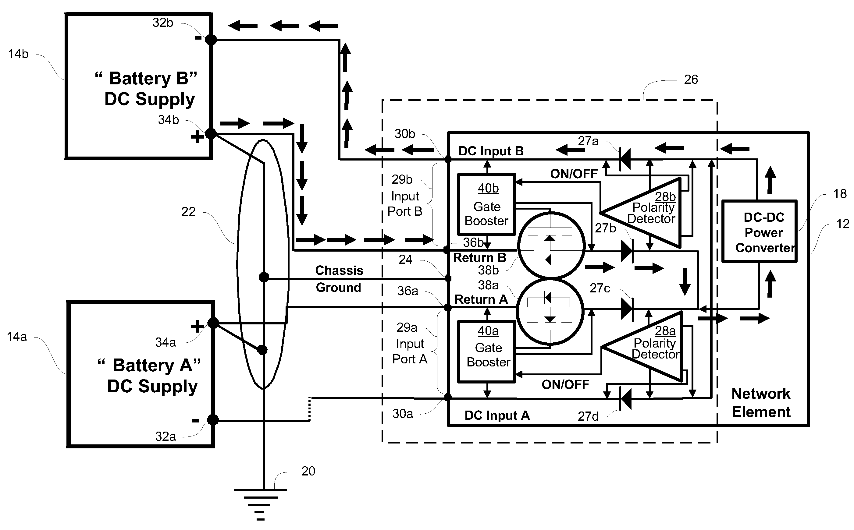
[0020]Before describing in detail exemplary embodiments that are in accordance with the present invention, it is noted that the embodiments reside primarily in combinations of apparatus components and processing steps related to implementing a system and method for battery return disconnect switch for network elements powered by a dual battery supply that prevents an excess current from affecting the building's vertical riser and ground when one battery is disconnected or the batteries are at unequal voltage levels. Accordingly, the system and method components have been represented where appropriate by conventional symbols in the drawings, showing only those specific details that are pertinent to understanding the embodiments of the present invention so as not to obscure the disclosure with details that will be readily apparent to those of ordinary skill in the art having the benefit of the description herein.

[0021]As used herein, relational terms, such as “first” and “second,”“top...


PUM


Abstract

A battery return disconnect (“BRD”) circuit for use with a battery supply having a plurality of electrically parallel inter-connecting batteries. The BRD circuit includes a plurality of DC input ports, a set of OR-ing diodes, a plurality of polarity detectors and a plurality of switches. Each input port includes a DC input terminal and a DC return terminal. Each OR-ing diode is connected to a DC input terminal or a DC return terminal and is forward-biased to when the BRD circuit is connected to a plurality of batteries having substantially the same voltage level. Each polarity detector monitors the bias of an OR-ing diode electrically connected to a corresponding DC input terminal. Each switch is connected to a DC return terminal and a polarity detector. Each switch is closed as long as the monitored OR-ing diode is forward-biased and open when the monitored OR-ing diode is reverse-biased.

Description

CROSS-REFERENCE TO RELATED APPLICATION[0001]The present invention is related to and claims priority to U.S. Provisional Patent Application No. 61 / 075,894, filed Jun. 26, 2008, entitled “BATTERY RETURN DISCONNECT: SOLUTION TO STOP RETURN CURRENT FLOWING INTO DISCONNECTED POWER PORT OF AN NE POWERED BY DUAL BATTERY PLANT,” the entire contents of which is incorporated herein by reference.STATEMENT REGARDING FEDERALLY SPONSORED RESEARCH OR DEVELOPMENT[0002]n / aFIELD OF THE INVENTION[0003]The present invention relates generally to a battery disconnect switch, and more specifically to a solid state disconnect switch to prevent excessive current on battery return leads of a network element powered by a dual battery supply.BACKGROUND OF THE INVENTION[0004]The telecommunication industry provides customers with constant, around the clock access to communication services. Downtime is not permitted or tolerated in this industry. As such, most communication systems require some form of redundancy...

Claims


Application Information

Patent Timeline
IPC IPC(8): H02H3/00
CPCH02H3/18H02J7/0031H02J7/0013H02H7/18H02J7/00304
Inventor PATEL, AMRISH
Owner CIENA
Why Eureka
Try Eureka