Method for preventing corrosion of contact and apparatus for preventing corrosion of contact

Inactive Publication Date: 2006-12-14
FUJITSU GENERAL LTD
View PDF10 Cites 2 Cited by
  • Summary
  • Abstract
  • Description
  • Claims
  • Application Information

AI Technical Summary

Benefits of technology

[0009] In order to prevent an erroneous determination and a malfunction from occurring in an apparatus in which the contact corrosion preventing apparatus 1 is disposed (hereinafter, referred to merely as “apparatus”), the contact corrosion preventing apparatus 1 of US 2005 / 0231858A removes corrosion of the contact 3, i.e., reduces the resistance of the contact. When corrosion of the contact 3 is detected, the comparator 6 causes the corrosion prevention current to pass through the detection conducting path until the potential of the detection conducting path 5 becomes lower than the predetermined potential VX, thereby removing corrosion of the contact 3. In other words, the removal of corrosion of the contact 3 is continued until a resistance at which the potential of the detection conducting path 5 is lower than the predetermined potential VX (hereinafter, referred to “predetermined resistance”) is attained. Even in a state where the resistance of the contact 3 is higher than the predetermined resistance, corrosion is removed to a degree at which an erroneous determination and malfunction of the apparatus can be prevented from occurring. In the contact corrosion preventing apparatus 1, namely, the corrosion prevention current is excessively passed to remove corrosion of the contact 3, thereby reducing the resistance of the contact 3. The passing of the corrosion prevention current causes the possibility that the apparatus performs an erroneous determination and a malfunction, and hence it is preferable to shorten the current passing time period. When the corrosion prevention current is excessively passed in this way, the lifetime of the contact corrosion preventing apparatus is shortened.
[0010] The invention provides a method for suppressing excessive corrosion prevention current from flowing for a long time and an apparatus therefor.

Problems solved by technology

When the corrosion prevention current is excessively passed in this way, the lifetime of the contact corrosion preventing apparatus is shortened.

Method used


Image

  • Method for preventing corrosion of contact and apparatus for preventing corrosion of contact
  • Method for preventing corrosion of contact and apparatus for preventing corrosion of contact
  • Method for preventing corrosion of contact and apparatus for preventing corrosion of contact

Examples


first embodiment

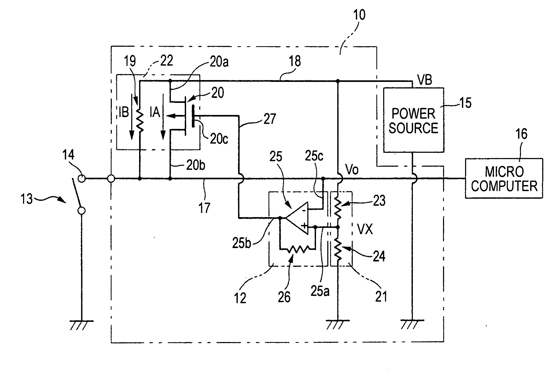
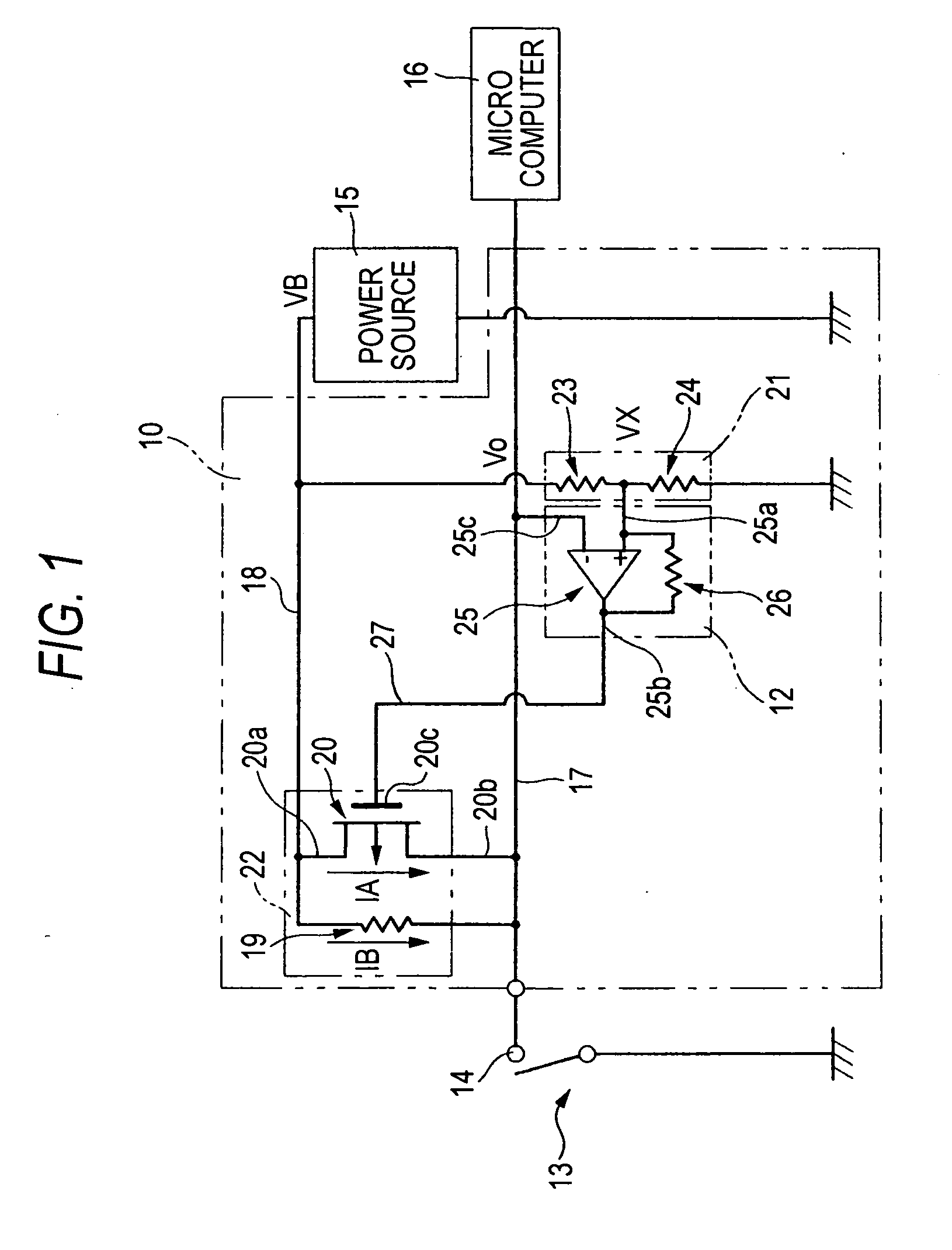
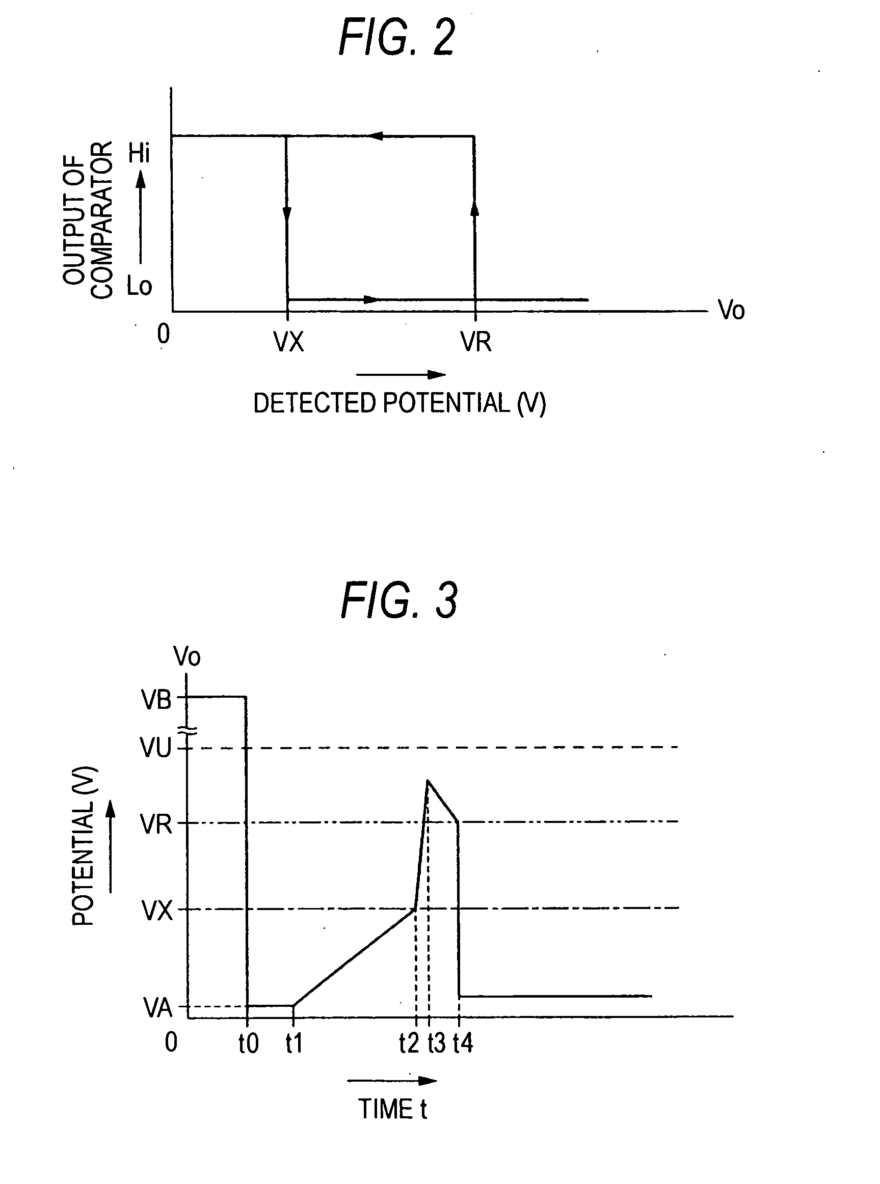
[0068]FIG. 1 is a circuit diagram schematically showing a contact corrosion preventing apparatus 10 of a FIG. 2 is a graph showing the output characteristic of a comparing and switching unit 12. In FIG. 2, the ordinate indicates the level of an output signal of the comparing and switching unit, and the abscissa indicates the potential. The contact corrosion preventing apparatus 10 is disposed in an apparatus which detects a connection state of a contact 14 included in a switch 13 or a connector. The contact corrosion preventing apparatus 10 detects corrosion and restoration of the contact 14. When corrosion of the contact 14 is detected, the contact corrosion preventing apparatus 10 passes a corrosion prevention current IA for removing corrosion of the contact 14, and, when restoration of the corroded contact 14 is detected, stops passing of the corrosion prevention current IA. The contact corrosion preventing apparatus 10 is an apparatus for removing corrosion of the contact 14, a...

second embodiment

[0102] The comparing and switching unit 12B is configured by the comparator 25. The comparing and switching unit 12B has a function of comparing the detection potential with a corrosion restoration potential VM. The comparing and switching unit 12B has a function of, when the detection potential becomes higher than the corrosion restoration potential VM, switching the output signal from Hi to Lo, and, when the detection potential becomes lower than the corrosion restoration potential VM, switching the output signal from Lo to Hi. The corrosion restoration potential VM which is a corrosion restoration threshold is a reference potential which is supplied from the reference voltage source 21 to the non-inverting input terminal 25a, and, for example, 1 V. The corrosion restoration potential VM is a potential at which corrosion and restoration of the contact 14 can be determined. Specifically, the corrosion restoration potential VM is set to be equal to or lower than the potential VU at ...

third embodiment

[0112] The microcomputer 16C which is stopping means has the same functions as the microcomputer 16B of the contact corrosion preventing apparatus 10B of the third embodiment, and further has the following function. The microcomputer 16C has a function of, when the number of current-passing operations becomes equal to or larger than a predetermined stop number which is a specified number, stopping the voltage supply of the power source 15. For example, the power source 15 is configured so that, when the voltage supply of the power source 15 is once stopped, the voltage is not supplied unless the user manually restarts the voltage supply.

[0113]FIG. 12 is a graph showing variation of the current of the detection conducting path 17 with respect to an elapsed time. FIG. 13 is a graph showing variation of a detection potential V3 with respect to an elapsed time. FIG. 14 is a graph showing output variation of the comparing and switching unit 12B with respect to an elapsed time. In FIG. 12...


PUM


Abstract

An apparatus for preventing corrosion of a contact includes a detection conducting path connected to the contact, a variable impedance unit and a comparing and switching unit. The variable impedance unit is connected to the detection conducting path. The variable impedance unit is switchable between (i) a first impedance used for passing a corrosion prevention current into the detection conducting path and (ii) a second impedance through used for passing a current, which is used for detecting a connection state of the contact, into the detection conducting path. The first impedance is lower than the second impedance. The comparing and switching unit compares a detected value with a corrosion threshold, compares the detected value with a restoration threshold and switches the variable impedance unit based on comparing results.

Description

CROSS-REFERENCE OF RELATE APPLICATIONS [0001] This application is based upon and claims the benefit of priority from Japanese Patent Application No.2005-99748 filed on Mar. 30, 2005, the entire contents of which are incorporated herein by reference. BACKGROUND OF THE INVENTION [0002] 1. Field of the Invention [0003] The present invention relates to a corrosion preventing method in which a corrosion prevention current for removing corrosion of a contact is passed to remove corrosion of a contact, thereby preventing corrosion of the contact, and an apparatus for the method. [0004] In the specification, “corrosion prevention current” is synonymous with a current for removing corrosion of a contact. [0005] 2. Description of the Related Art [0006] In an apparatus which can detect a connection state of a contact of a switch, an erroneous determination and malfunction due to an increase of the resistance of the switch which is caused by corrosion of the contact become problematic. Recently...

Claims


Application Information

Patent Timeline
IPC IPC(8): H02H5/04
CPCH01H1/605
Inventor KOMATSU, KAZUHIROKASAME, TOMOHIDEOONISHI, KOUJI
Owner FUJITSU GENERAL LTD
Why Eureka
Try Eureka