Methods for deploying stents in bifurcations

a technology of stents and bifurcations, applied in the field of stent delivery, can solve the problems of particularly difficult stent delivery by the physician, and achieve the effect of reducing or eliminating the possibility of wire entanglement or cross-over

Inactive Publication Date: 2009-12-31
BOSTON SCI SCIMED INC
View PDF102 Cites 63 Cited by
  • Summary
  • Abstract
  • Description
  • Claims
  • Application Information

AI Technical Summary

Benefits of technology

[0006]An object of the present invention is to provide a method of deploying a stent in a vessel bifurcation which method substantially reduces or eliminates the possibility of wire entanglement or cross-over when deploying the stent.

Problems solved by technology

Implanting stents in bifurcations is particularly problematic because of the need to precisely locate the stent both longitudinally and radially in the bifurcation.
However, in such a two-wire technique, due to the tortuosity of the vascular system, the physician must torque the delivery system in order to deliver the guidewires to their correct location.
Because of this torquing, the two guidewires frequently tend to cross over one another and / or entangle during their use for guiding the stent delivery device.
Such an entanglement or crossover, if it should occur, may result in an inability of the device to be delivered by the physician, requiring the procedure to be started anew.

Method used


Image

  • Methods for deploying stents in bifurcations
  • Methods for deploying stents in bifurcations
  • Methods for deploying stents in bifurcations

Examples


Embodiment Construction

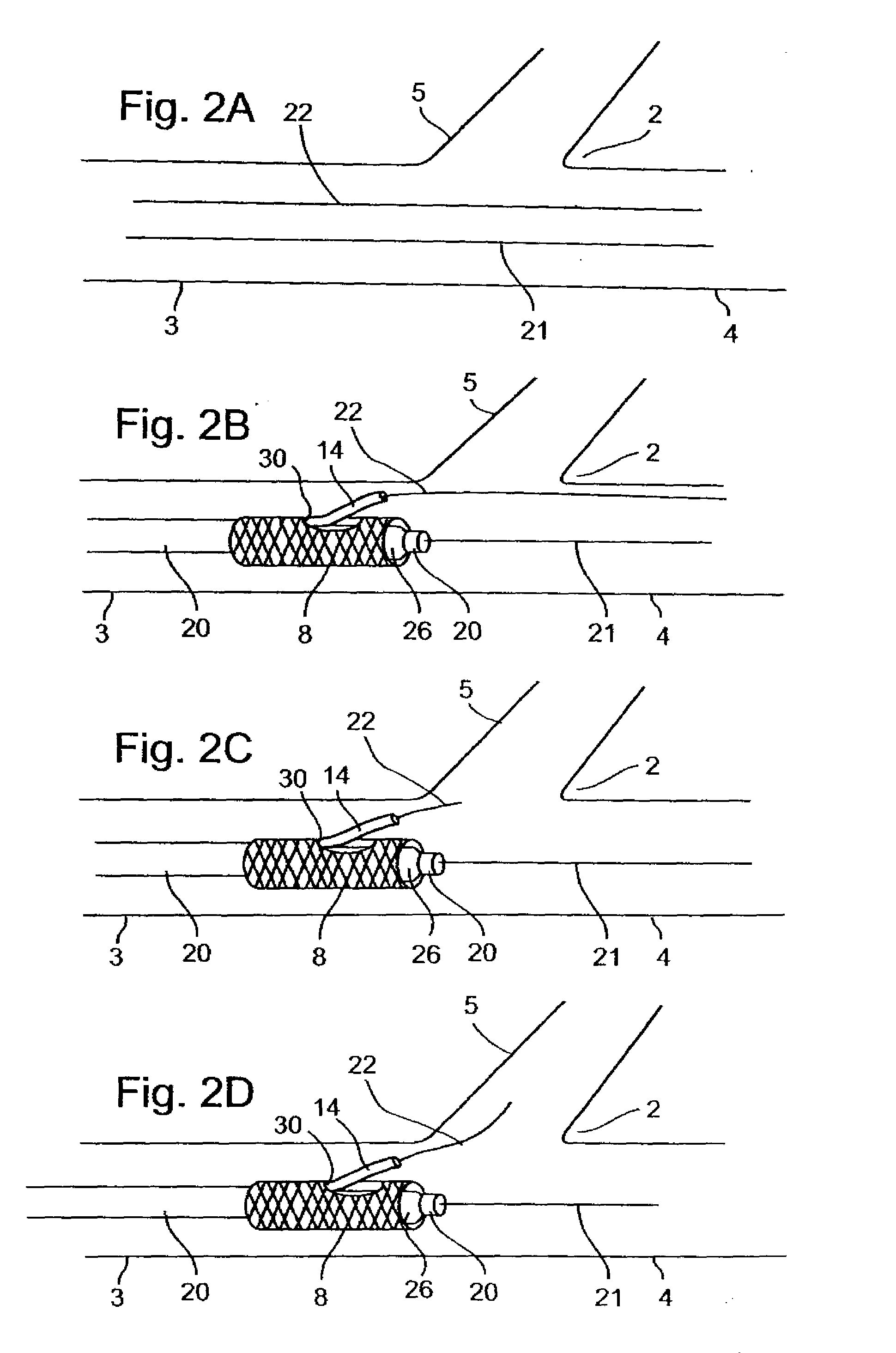
[0026]The present invention is of a method for deploying a stent at or near a bifurcation. Specifically, the method of the present invention allows insertion of two wires into two branches of a vessel while avoiding wire entanglement.

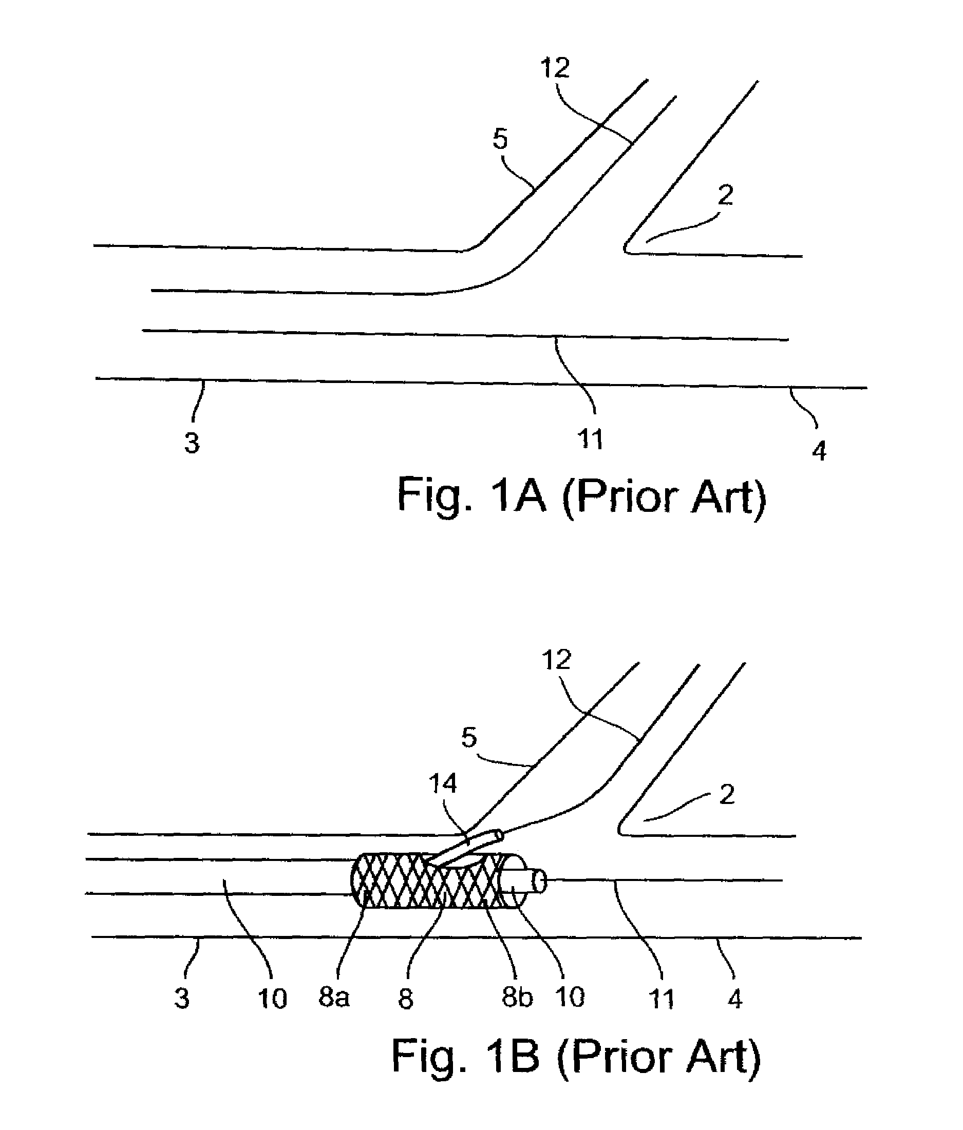
[0027]For purposes of better understanding the present invention, as illustrated in FIGS. 2-5 of the drawings, reference is first made to the two-wire method of deploying a stent in a vessel bifurcation (i.e. the prior art) as illustrated in FIGS. 1A and 1B. In the example illustrated in FIGS. 1A and 1B, the bifurcation, generally designated 2, involves a main vessel 3, which splits into a main vessel continuation 4, and a branch vessel 5. The point at which the two branches 4, 5 intersect is commonly called the “saddle point” of the bifurcation.

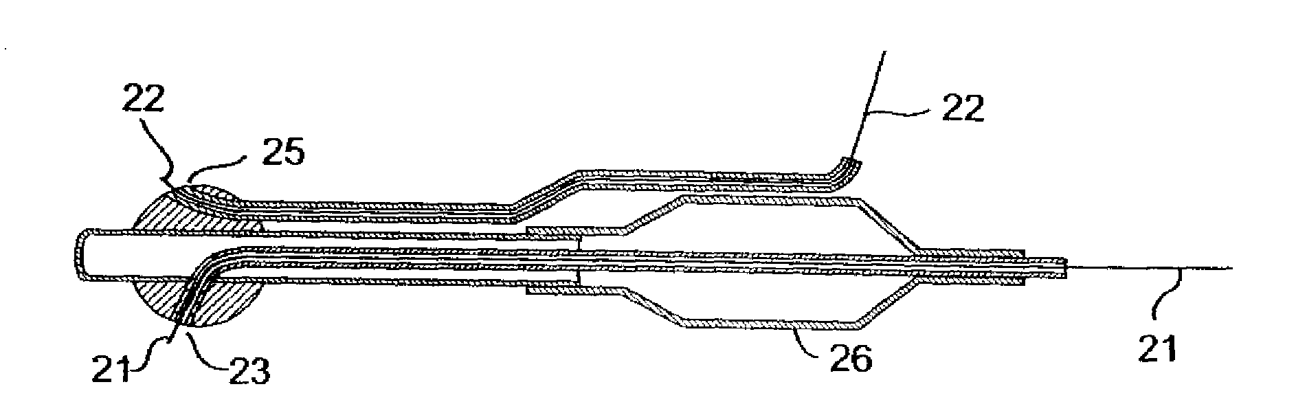
[0028]The stent to be deployed is generally designated 8. It includes a proximal end 8A to be deployed in the main vessel 3, and a distal end 8B to be deployed in the main vessel continuation 4. For this purpose...


PUM


Abstract

A method of deploying a stent in a bifurcation includes introducing two guidewires through the main vessel and using the two guidewires for guiding a dual lumen catheter carrying a stent first to an initial position proximal to the stent deployment position, retracting one wire, and projecting it from the catheter and through a side of the stent a branch guidewire into the second branch vessel, and then moving the catheter to the predetermined deployment position while guided by the main guidewire in the first branch vessel, and the branch guidewire in the second branch vessel. The stent is then expanded, and the catheter is removed with the stent remaining in its deployed position An alternative embodiment includes introducing one wire, advancing the system over the one wire and subsequently introducing the second wire.

Description

[0001]This application is a continuation of U.S. patent application Ser. No. 10 / 320,719, filed Dec. 17, 2002, which claims the benefit under U.S.C. 119 of U.S. Provisional Patent Application Ser. No. 60 / 339,802, filed Dec. 17, 2001. U.S. patent application Ser. No. 10 / 320,719, filed Dec. 17, 2002, is also a continuation in part of U.S. patent application Ser. No. 09 / 816,690, filed Mar. 22, 2001, now issued U.S. Pat. No. 6,682,536, which is a continuation in part of U.S. patent application Ser. No. 09 / 533,616, filed Mar. 22, 2000, now abandoned. U.S. patent application Ser. No. 10 / 320,719, filed Dec. 17, 2002, is also a continuation in part of pending U.S. patent application Ser. No. 09 / 741,761, filed Dec. 18, 2000, now issued U.S. Pat. No. 6,596,020, which is a continuation of abandoned U.S. patent application Ser. No. 09 / 325,996, filed Jun. 4, 1999, which is a continuation in part of expired U.S. PCT / US99 / 00835, filed Jan. 13, 1999, published as WO99 / 36002 on Jul. 22, 1999, which c...

Claims


Application Information

Patent Timeline
Patent Type & Authority Applications(United States)
IPC IPC(8): A61F2/84A61B17/00A61F2/00A61M25/09
CPCA61B2017/00469A61F2/856A61F2/954A61F2/958A61M2025/018A61M25/01A61M25/09A61M25/09041A61F2250/0098
Inventor VARDI, GIL
Owner BOSTON SCI SCIMED INC
Why Eureka
Try Eureka