Petroleum-based Thermoelectric Energy Conversion System

a technology of thermoelectric energy conversion and pumping system, which is applied in the direction of geothermal energy generation, mechanical power devices, machines/engines, etc., can solve the problems of increasing operating costs and mechanical complexity, electrical cables are subject to damage from marine life, and the corrosive nature of oil and/or natural is sufficiently reduced

Inactive Publication Date: 2010-01-07
LOCKHEED MARTIN CORP
View PDF2 Cites 6 Cited by
  • Summary
  • Abstract
  • Description
  • Claims
  • Application Information

AI Technical Summary

Benefits of technology

[0016]In some embodiments, the energy conversion system removes enough heat from the petroleum products that flow through a conduit thermally coupled to the hot zon

Problems solved by technology

A challenge associated with extraction of oil and natural gas in remote areas is powering the drilling and pumping equipment when there is no convenient means of providing electricity.
Unfortunately, pumps located at the platform are less mechanically efficient.
As a result, such a pump configuration increases operating costs as well as mechanical complexity.
Fir

Method used


Image

  • Petroleum-based Thermoelectric Energy Conversion System
  • Petroleum-based Thermoelectric Energy Conversion System
  • Petroleum-based Thermoelectric Energy Conversion System

Examples


Embodiment Construction

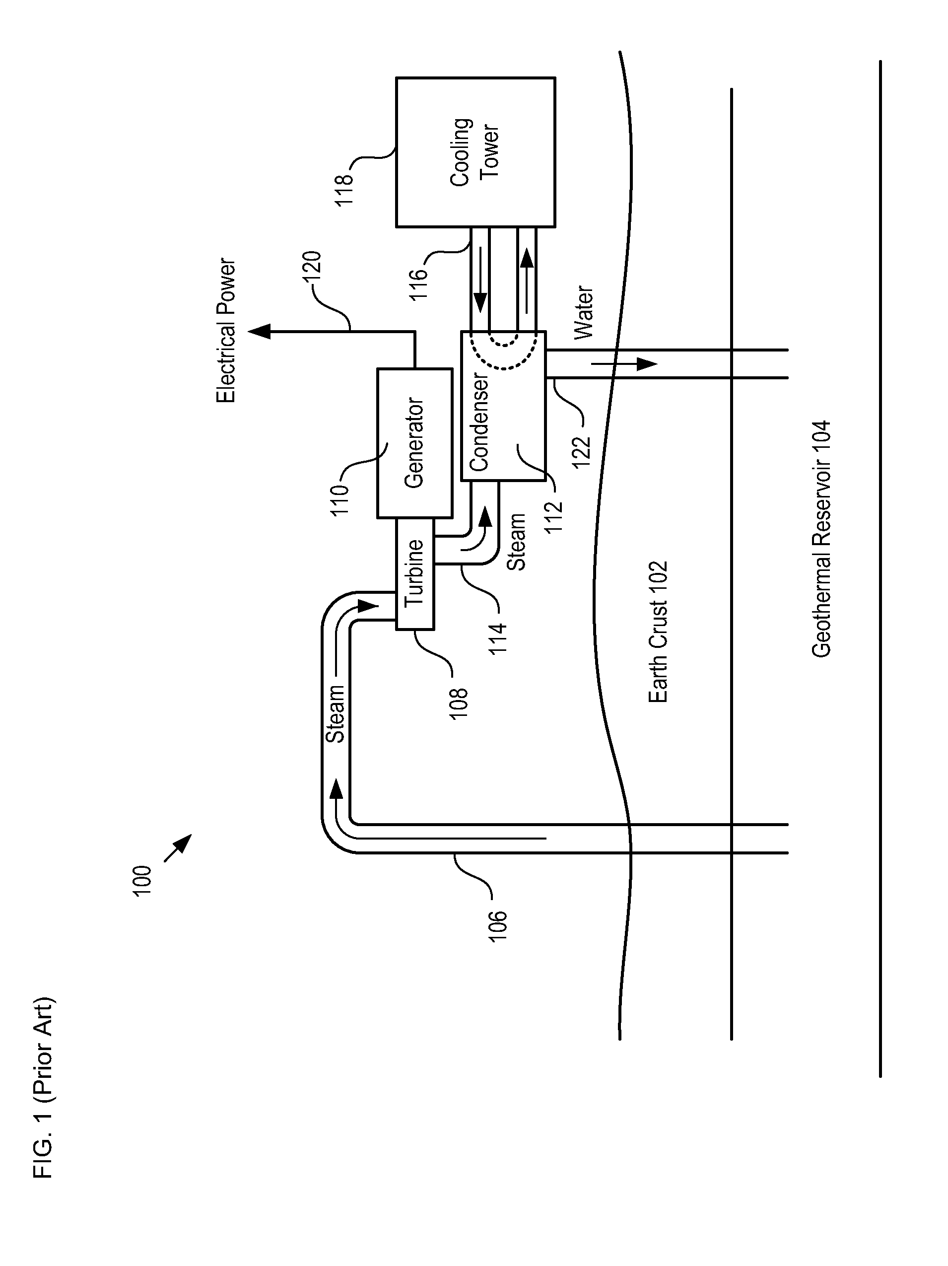
[0026]FIG. 1 depicts a schematic diagram of details of a prior-art geothermal energy conversion system. Energy system 100 comprises inlet pipe 106, turbine 108, generator 110, condenser 112, couplings 114 and 116, cooling tower 118, and outflow pipe 122. In some embodiments, a water pump is coupled to the outflow of condenser 112 to drive the return water to greater depths or to facilitate flow in a very long or narrow outflow pipe 122.

[0027]In operation, steam from geothermal reservoir 104, which resides below earth crust 102, is conveyed to turbine 108 by inlet pipe 106. The steam turns turbine blades within the turbine. Turbine 108 is operatively coupled to generator 110. As turbine 108 turns generator 110, the generator produces electrical energy. This electrical energy is conveyed to an end user on output cable 120.

[0028]As the steam passes through turbine 108, it is conveyed to condenser 112 via coupling 114. At condenser 112, the steam is cooled by refrigerant fluid that circ...


PUM


Abstract

A system for generating electrical energy based on a temperature differential between petroleum products extracted from a geothermal reservoir and water from a region of a body of water is disclosed. Some embodiments comprise a submerged pump and a submerged OTEC system, wherein the OTEC system provides locally generated electrical energy to the pump.

Description

CROSS REFERENCE TO RELATED APPLICATIONS[0001]This case claims priority to: U.S. Provisional Patent Application Ser. No. 61 / 078,202, filed Jul. 3, 2008 (Attorney Docket: 711-214US), which is incorporated by reference.[0002]In addition, the underlying concepts, but not necessarily the language, of the following cases are incorporated by reference:[0003](1) U.S. patent application Ser. No. 12 / 396,349, filed Mar. 2, 2009 (Attorney Docket: 711-260US); and[0004](2) U.S. patent application Ser. No. 12 / 411,824, filed Mar. 26, 2009 (Attorney Docket: 711-263US).[0005]If there are any contradictions or inconsistencies in language between this application and one or more of the cases that have been incorporated by reference that might affect the interpretation of the claims in this case, the claims in this case should be interpreted to be consistent with the language in this case.FIELD OF THE INVENTION[0006]The present invention relates to pump systems in general, and, more particularly, to pet...

Claims


Application Information

Patent Timeline
IPC IPC(8): F03G4/00
CPCF03G7/04Y02E10/34Y02E10/10F03G7/05Y02E10/30
Inventor NAGURNY, NICHOLAS J.LEVINGS, NATALIEGREER, LANCE
Owner LOCKHEED MARTIN CORP
Why Eureka
Try Eureka